A clamp specially used for a low-frequency electro-hydraulic servo fatigue testing machine

A fatigue testing machine, electro-hydraulic servo technology, applied in the direction of measuring devices, instruments, scientific instruments, etc., can solve the problems of troublesome replacement, labor-intensive, low efficiency, etc., and achieve the effect of low manufacturing cost, convenient use, and easy installation

Inactive Publication Date: 2014-10-29
BAOSTEEL GRP NANTONG WIRE PROD
View PDF7 Cites 2 Cited by
  • Summary
  • Abstract
  • Description
  • Claims
  • Application Information

AI Technical Summary

Problems solved by technology

The disadvantage is that ordinary fixtures are bulky and troublesome to replace, requiring two people to operate together, which is time-consuming, manpower-intensive and inefficient

Method used


Image

  • A clamp specially used for a low-frequency electro-hydraulic servo fatigue testing machine
  • A clamp specially used for a low-frequency electro-hydraulic servo fatigue testing machine

Examples


Embodiment Construction

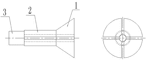
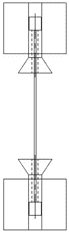
[0015] The present invention will be further described below in conjunction with the accompanying drawings. Special fixture for low-frequency electro-hydraulic servo fatigue testing machine, including chuck 1, chuck 2 and jacket 3.

[0016] Such as figure 1 As shown, the structure of the special fixture for the low-frequency electro-hydraulic servo fatigue testing machine is: the chuck 2 is a cylindrical cavity with a through hole in the middle. Any end of the cartridge 2 is provided with a collet 1 integrally formed with the cartridge 2 . Chuck 1 is a trumpet-shaped cylinder with a through hole in the middle. The other end of the cartridge 2 is also connected with a jacket 3 , integrally formed with the cartridge 2 . The jacket 1 is a cylindrical cavity with a through hole in the middle. The outer cylindrical diameter of the jacket 3 is 1 mm smaller than that of the chuck 2 . The diameters of the through holes of the collet 1 and the cartridge 2 are consistent. Four ope...


PUM

PropertyMeasurementUnit
Groove widthaaaaaaaaaa

Abstract

A clamp specially used for a low-frequency electro-hydraulic servo fatigue testing machine is disclosed. The clamp comprises a clamping head (1), a clamping cylinder (2) and a jacket (3). The external cylindrical diameter of the jacket is 1 mm smaller than the external cylindrical diameter of the clamping cylinder, so that the clamp is provided with directivity and is convenient to install. The surface of the clamping head is evenly provided with four open slots by adopting the 90 degrees as a boundary, and therefore the clamp has elasticity, and a steel wire in the clamp can be tightly clamped when the clamp clamps the steel wire. The clamping head and the cylinder are provided with through holes and the jacket is free of through holes, thus limiting the length of the steel wire extending inside so as to perform spacing. The clamp has characteristics of simple configuration, using convenience and low manufacturing cost.

Description

technical field [0001] The invention relates to the field of steel wire detection, in particular to a special fixture for a low-frequency electro-hydraulic servo fatigue testing machine. Background technique [0002] Fatigue testing machine is a machine mainly used to test the fatigue performance of metals and their alloy materials at room temperature under tension, compression, or tension and compression alternating loads. For the axial fatigue performance test of metal materials, most of the equipment currently used is electro-hydraulic servo fatigue testing machine. Usually the fatigue testing machine has a wedge grip, a flat push grip and a barrel grip. The disadvantage is that ordinary fixtures are heavy and cumbersome to replace, requiring two people to operate together, which is time-consuming, manpower-intensive and inefficient. Contents of the invention [0003] In order to overcome the deficiencies of the prior art above, the present invention provides a speci...

Claims


Application Information

Patent Timeline
IPC IPC(8): G01N3/04
Inventor 裴广顺
Owner BAOSTEEL GRP NANTONG WIRE PROD
Why Eureka
Try Eureka