Momentum wheel based on moving coil motor

A momentum wheel and moving coil technology, applied in the field of momentum wheels, to achieve stable operation, strong controllability, and performance change

Active Publication Date: 2014-10-29
XI AN JIAOTONG UNIV
View PDF6 Cites 2 Cited by
  • Summary
  • Abstract
  • Description
  • Claims
  • Application Information

AI Technical Summary

Problems solved by technology

[0004] In order to solve the above-mentioned problems in the prior art, the object of the present invention is to provide a momentum wheel based on a moving coil motor; during the operation of the momentum wheel, the input is a single-phase DC voltage, the current in the coil is relatively stable, and the operation fluctuation is small ; Since the relative position of the momentum wheel rotor and the stator does not affect the magnetic circuit, there is no need for an external circuit for real-time measurement of the rotor position, reducing the complexity of the circuit; since the momentum wheel stator uses a whole piece of NdFeB permanent magnet, the space where the coil is located The magnetic field strength is high, and it can still provide a large torque in the case of a small current

Method used


Image

  • Momentum wheel based on moving coil motor
  • Momentum wheel based on moving coil motor

Examples


Embodiment Construction

[0020] Combine below figure 1 , figure 2 The present invention is further described in detail with specific examples.

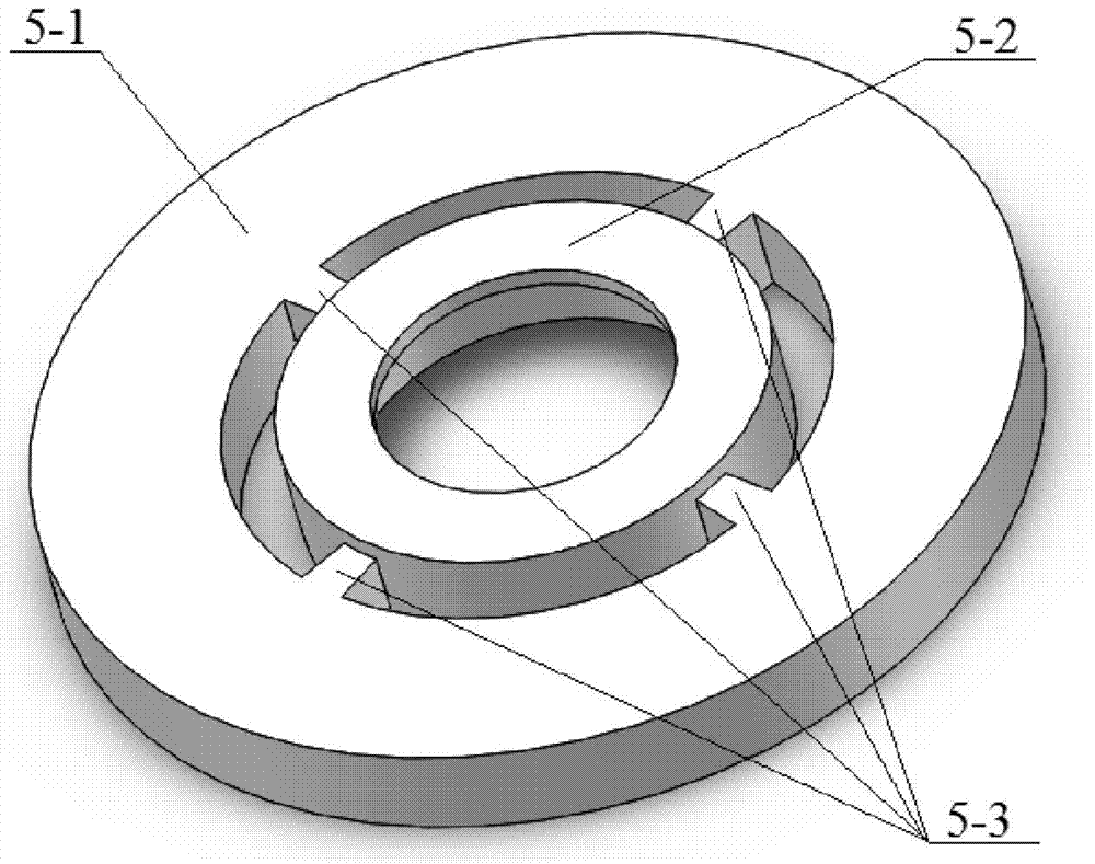
[0021] Such as figure 1 As shown, a momentum wheel based on a moving coil motor in the present invention includes a housing base 4, a housing upper cover 1 fixed on the housing base 4, and a cavity is formed between the housing upper cover 1 and the central support column of the housing base 4 , the inner ring of the rotating shaft 7 is fixed on the outer peripheral ring of the center support column of the shell base 4 in the cavity, and the rotor core 5 is fixed on the outer ring of the rotating shaft 7 in the cavity, and the coil 2 is wound on the rotor iron core 5, and the rotor The iron core 5 and the coil 2 jointly constitute the rotor part of the momentum wheel, and the stator part of the motor, that is, the permanent magnet 3, is respectively fixed on the upper and lower parts of the rotor iron core 5 and the coil 2, the inner wall of the casing upp...


PUM


Abstract

Disclosed is a momentum wheel based on a moving coil motor. The momentum wheel based on the moving coil motor is characterized in that a cavity is formed between an upper cover of a housing and a center support pillar of a housing bottom seat, an inner ring of a rotation shaft is fixed on the periphery of the center support pillar of the housing bottom seat, located in the cavity, a rotor iron core with a coil wound around is fixed on an outer ring of the rotation shaft in the cavity, the rotor iron core and the coil form a rotor portion of the momentum wheel, stator portions of the motor, which are permanent magnets, are respectively fixed on the upper portions and the lower portions of the rotor iron core and the coil, the upper cover of the housing and the inner wall of the housing bottom seat, the magnetizing direction of each permanent magnet is along the vertical direction, and a slide ring is placed in the cavity between the rotor iron core and the housing bottom seat. During the running process of the momentum wheel based on the moving coil motor, single phase direct voltage is input into the momentum wheel, and therefore electric current running fluctuation in the coil is small; relative positions of rotors and stators can not influence a magnetic circuit, and therefore external circuits which monitor positions of the rotors in real time are not needed, and circuit complexity is reduced; whole permanent magnets are used as the stators, and therefore magnetic field intensity in a space where the coil is located is high, and large torque can still be provided under the circumstance that electric currents are small.

Description

technical field [0001] The invention relates to the technical field of momentum wheels, in particular to a momentum wheel based on a moving coil motor. Background technique [0002] The existing momentum wheels mainly use brushless DC motors as the power source. The working principle of these DC motors is: the stator is a coil wound iron core, the coil is wound in a three-phase manner, and the three-phase DC power is fed into the power supply. The DC waveform is a square wave, three-phase The phase difference between them is 120 degrees. When working, a current is applied to generate a rotating magnetic field between the coil and the air gap of the permanent magnet of the rotor to drive the permanent magnet to rotate. Its disadvantage as a momentum wheel: it is necessary to measure the position of the motor rotor during operation to adjust the input current waveform and phase of the motor, so a complex drive circuit is required; due to the current commutation, the operation...

Claims


Application Information

Patent Timeline
Patent Type & Authority Applications(China)
IPC IPC(8): H02K21/24
Inventor 孙剑郭彦昊
Owner XI AN JIAOTONG UNIV
Why Eureka
Try Eureka