Novel spring mattress manufacture method

A manufacturing method and mattress technology, applied to spring mattresses, mattresses, stuffed mattresses, etc., can solve problems such as easy breakage of support springs, poor user feeling, and weak comfort, so as to ensure stability, Enhanced comfort, unbreakable effect

Inactive Publication Date: 2014-11-05
聂坤怀
View PDF5 Cites 0 Cited by
  • Summary
  • Abstract
  • Description
  • Claims
  • Application Information

AI Technical Summary

Problems solved by technology

figure 2 for figure 1 The schematic diagram of the lateral force, when the "community of force" is subjected to a lateral force F from right to left, the component force f of the lateral force F acts on parts B, C, D and E. The disadvantages are: ①The lateral force makes the middle row The circular springs are staggered by horizontal extrusion, which will cause the concave springs in each row to be unevenly arranged; Decreased lifespan
[0005] In addition, the overall spring mattress formed by the "community of force" and the surrounding frame (upper and lower surrounding frames), supporting springs and clamping nails has the following disadvantages: ①The diameter of the steel wire of the surrounding frame is about 5mm, while the round The diameter of the spring is 1.9mm. The elasticity of the "community under force" formed by the round spring and the through spring is stronger than that of the surrounding frame. Under the action of the same force, the deformation of the spring assembly is greater than that of the surrounding frame. The degree of deformation is different, and the clamping piece is made of rigid material, which is easy to be stretched and deformed; ②After

Method used


Image

  • Novel spring mattress manufacture method
  • Novel spring mattress manufacture method
  • Novel spring mattress manufacture method

Examples


Embodiment Construction

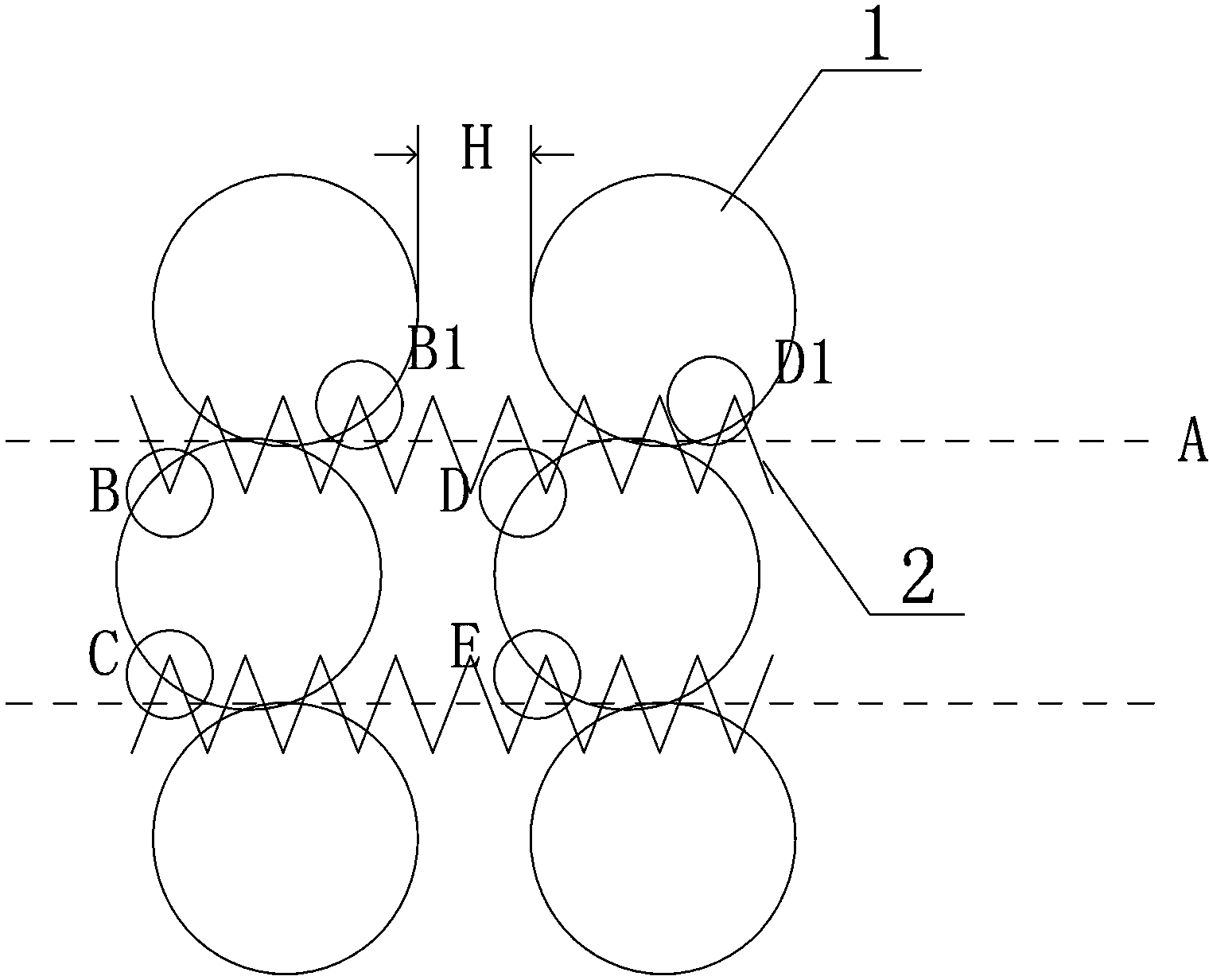
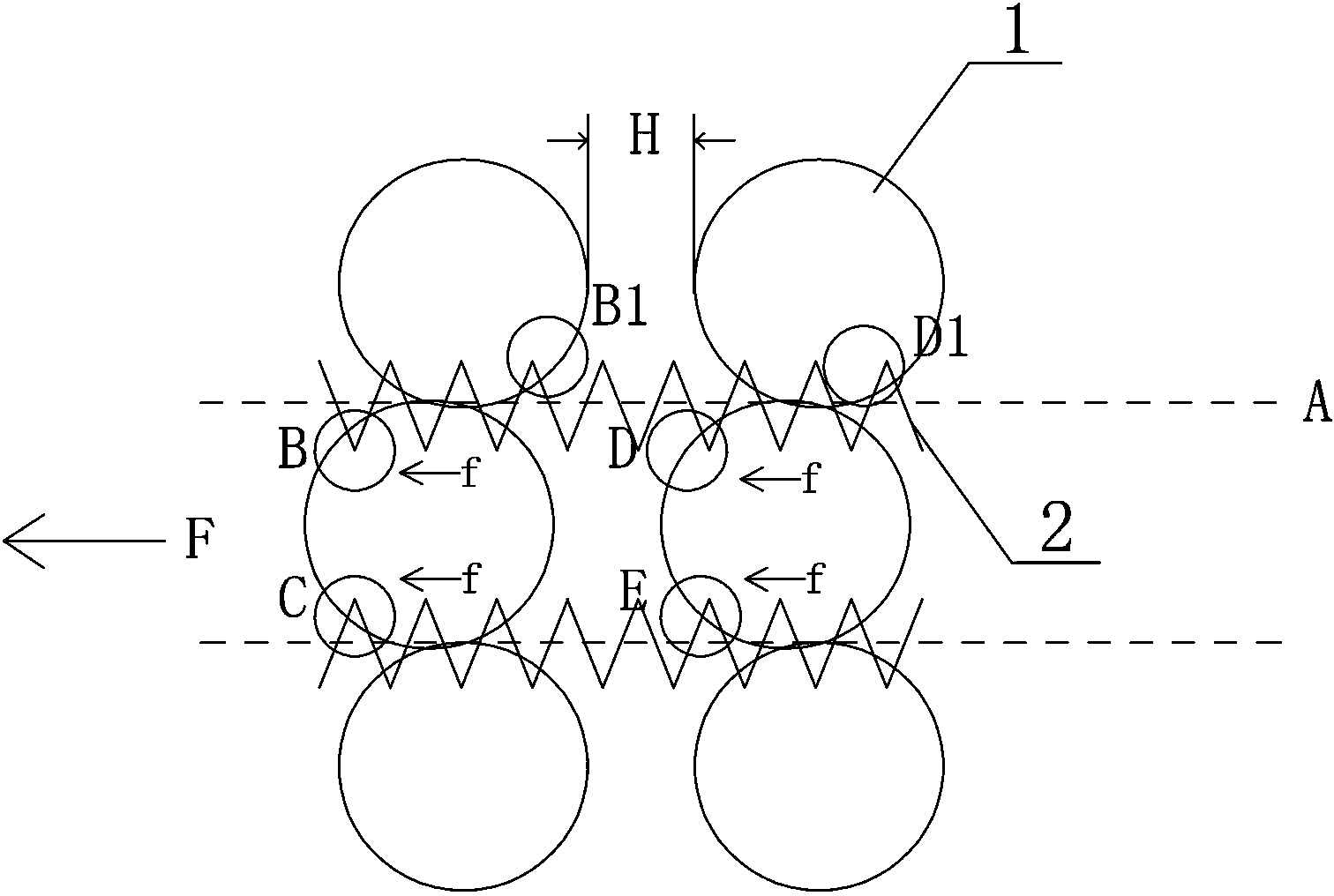
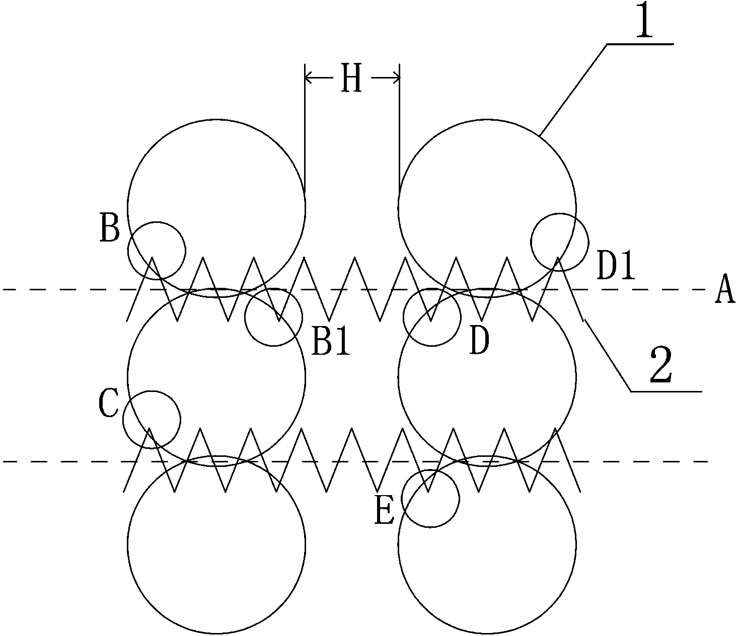
[0023] A new type of spring mattress production method, the main equipment is a spring threading machine, such as image 3 , Figure 4 and Figure 5 As shown, the steps are as follows:

[0024] (1) Arranging the concave springs: Arrange the concave springs on the workbench of the spring threading machine to form a rectangular array in horizontal rows and vertical rows, and the distance between adjacent concave springs in the horizontal row is H; The upper and lower support rings of the concave springs 1 in two adjacent rows are close to each other or cross;

[0025] (2) String springs: use a spring threading machine to insert the threaded springs 2 horizontally into the upper support rings of the concave springs 1 that are close to each other or cross each other, so that two adjacent rows of concave springs are connected to each other; in the spring stringing process In the two upper support rings adjacent in the longitudinal direction, the penetration contact part B and th...


PUM

PropertyMeasurementUnit
Diameteraaaaaaaaaa
Diameteraaaaaaaaaa
Free heightaaaaaaaaaa

Abstract

The invention belongs to the technical field of filled mattresses and discloses a novel spring mattress manufacture method. The novel spring mattress manufacture method is characterized in that in same two horizontal adjacent upper support rings and in the spring stringing process, penetrating-in contact parts of a penetrating spring and two upper support rings are respectively positioned at both sides of an axis of a thread of the penetrating spring, and penetrating-out contact parts of the penetrating spring and the two upper support rings are respectively positioned at the both sides of the axis of thread. Compared with an existing haphazard winding method or a winding method mentioned in background, a winding method disclosed by the invention is researched by analyzing stress conditions of the support rings and the penetrating spring so that the structure of an entire spring core is firm and stress is balanced. In addition, a rebar enclosure frame with the strong rigidity, a clamp chip and a counterpressure spring are eliminated, a round spring has the elasticity, the rebar enclosure frame does not have the elasticity, and therefore, the deformation quantity of the penetrating spring is relatively small and the penetrating spring is not easy to damage when a spring net with the structure deforms.

Description

technical field [0001] The invention belongs to the technical field of stuffed mattresses. Background technique [0002] Spring mattress is a bedding made of spring and soft padding as the inner core material, and the outer cover is made of fabric fabric or soft mat. Spring mattresses have a relatively even and reasonable distribution of body support, which can not only play a sufficient supporting role, but also ensure a reasonable physiological curvature of the spine, and has become the mainstream stuffed mattress. [0003] Existing spring mattresses usually consist of an upper frame, a lower frame, a circular spring, a threaded spring, a support spring and a clamping piece. The traditional spring mattress is as follows: firstly, the concave springs are arranged according to the width direction of the mattress. into multiple rows, and then use spiral springs to connect the upper and lower support rings (that is, upper and lower support rings) of two adjacent rows of conca...

Claims


Application Information

Patent Timeline
IPC IPC(8): A47C27/06A47C27/07A47C27/05
Inventor 聂坤怀聂颖聂波
Owner 聂坤怀
Why Eureka
Try Eureka