Medical sputum aspirator

A technology of absorber and sputum, which is applied in the field of medical sputum absorber, can solve the problems of bulky, unrealistic sputum aspirator, complex structure of sputum aspirator, etc. Effect

Inactive Publication Date: 2014-11-05
上海伟阳纸业有限公司
View PDF0 Cites 3 Cited by
  • Summary
  • Abstract
  • Description
  • Claims
  • Application Information

AI Technical Summary

Problems solved by technology

The traditional sputum suction device is a suction tube combined with a negative pressure system. This kind of sputum suction device itself has a complex and bulky structure. It is very unrealistic to be equipped with such a sputum suction device whether it is an emergency room or a family or school to de

Method used


Image

  • Medical sputum aspirator
  • Medical sputum aspirator
  • Medical sputum aspirator

Examples


Embodiment approach 1

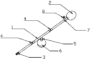
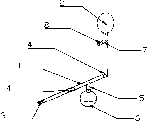
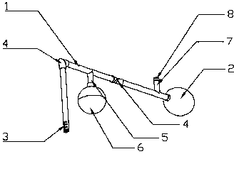
[0022] Implementation mode one: if Figure 1-6 As shown, the medical sputum absorber includes a suction pipe 1 and a pressure ball 2 connected to the tail end of the suction pipe 1. The front end of the suction pipe 1 is a blunt end, and several through holes 3 are evenly distributed on the side wall. There are two sections of half-hose 4, and the half-hose 4 is provided with creases. When the half-hose 4 has a fold angle ≥ 90o, the half-hose 4 is closed, and when the half-hose 4 is straightened, the half-hose 4 conduction, a branch pipe 5 is provided between the two halves of the hose 4, the branch pipe 5 is connected with a sputum storage device 6, and an exhaust pipe 7 is provided at the joint between the tail end of the suction pipe 1 and the pressure ball 2, and the exhaust pipe 7 is provided with a There is one-way valve 8. The sputum storage device 6 is detachably connected to the branch pipe 5, and the lower part of the sputum storage device 6 can be unscrewed. There...

Embodiment approach 2

[0028] Implementation mode two: if Figure 7 As shown, the medical sputum absorber includes a suction pipe 1 and a pressure ball 2 connected to the tail end of the suction pipe 1. The front end of the suction pipe 1 is a blunt end, and several through holes 3 are evenly distributed on the side wall. Two valves 9 are provided, and a branch pipe 5 is arranged between the two valves 9. The branch pipe 5 is connected with a sputum storage device 6. An exhaust pipe 7 is provided at the connection between the tail end of the suction pipe 1 and the pressure ball 2. The exhaust pipe 7 There is a one-way valve 8 on it. The sputum storage device 6 is detachably connected to the branch pipe 5, and the lower part of the sputum storage device 6 can be unscrewed. Be detachable connection between valve 9 and suction pipe 1.

[0029] Instructions:

[0030] Close the valve 9 at the end of the pressure ball 2, squeeze the pressure ball 2, and exhaust the air under the action of the one-way v...


PUM

PropertyMeasurementUnit
Chamferaaaaaaaaaa

Abstract

The invention relates to a portable medical instrument, in particular to a medical sputum aspirator. The traditional sputum aspirator employs a suction tube used with a negative pressure system; a body of the traditional sputum aspirator is complex in structure and heavy; the traditional sputum aspirator is very impractical for preparation in response to emergencies in both emergency treatment and families or schools. The medical sputum aspirator comprises a suction tube and a pressure bulb connected to the tail end of the suction tube; the front end of the suction tube is blunt; the sidewall of the suction tube is provided with a plurality of through holes; two half hoses are arranged on the suction tube and are provided with creases; when the half hoses are doubled at the angle not smaller than 90 degrees, the half hoses are closed; when straightened, the half hoses are open; a branch tube is disposed between the half hoses and is connected with a sputum storage device; an exhaust tube is disposed at the connection of the tail end of the suction tube and the pressure bulb; a one-way valve is disposed on the exhaust tube. The medical sputum aspirator is simple in structure and convenient to use, allows emergencies to be conveniently coped with, and is widely applicable to use in outdoor emergency treatment and emergencies in families and schools.

Description

technical field [0001] The invention relates to a portable medical device, in particular to a medical sputum absorber. Background technique [0002] Sputum blocking the airway can cause breathing difficulties and even suffocation, which is the most common symptom of respiratory diseases. The traditional sputum aspirator is a suction tube combined with a negative pressure system. The structure of this sputum aspirator is complex and bulky. It is very unrealistic to be equipped with such a sputum aspirator whether it is an emergency room or a family or school to deal with emergencies. However, after sudden sputum congestion causes dyspnea, if not treated in time, the consequences are often very serious. Therefore, a simple sputum suction device that is easy to equip and carry is needed to facilitate different environments to deal with such sudden and strong symptoms. . Contents of the invention [0003] The technical problem to be solved by the present invention is how to ...

Claims


Application Information

Patent Timeline
IPC IPC(8): A61M1/00
CPCA61M1/75A61M1/82
Inventor 程齐
Owner 上海伟阳纸业有限公司
Why Eureka
Try Eureka