Hemodialysis upper limb fixing device
A fixation device and hemodialysis technology, applied in dialysis systems, etc., can solve problems such as increased workload of medical staff, pain and fear of patients, increased venous pressure, etc., achieve good fixation effect and avoid discomfort
- Summary
- Abstract
- Description
- Claims
- Application Information
AI Technical Summary
Problems solved by technology
Method used
Image

Examples
Embodiment Construction
[0012] The present invention is described in further detail now in conjunction with accompanying drawing. These drawings are all simplified schematic diagrams, which only illustrate the basic structure of the present invention in a schematic manner, so they only show the configurations related to the present invention.
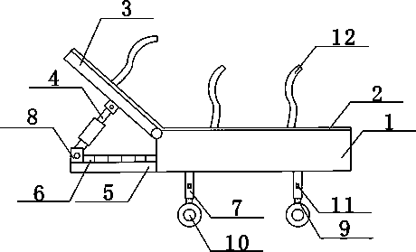
[0013] Such as figure 1 The preferred embodiment of the shown hemodialysis upper limb fixation device of the present invention comprises an upper bracket 3 and a lower bracket 1, the upper bracket 3 and the lower bracket 1 are hinged, and the upper bracket 3 and the lower bracket 1 surfaces are all provided with a non-woven fabric layer 2, There are also several through holes on the surface of the upper bracket 3 and the lower bracket 1, and a fixed rope 12 is connected in the through hole. The fixed rope 12 passes through the non-woven fabric layer 2 and extends outside. The fixed rope 12 is made of elastic material. The fixed rope 12 is located on the One e...
PUM
 Abstract
Description
Claims
Application Information
 - R&D
- Intellectual Property
- Life Sciences
- Materials
- Tech Scout
- Unparalleled Data Quality
- Higher Quality Content
- 60% Fewer Hallucinations
Browse by: Latest US Patents, China's latest patents, Technical Efficacy Thesaurus, Application Domain, Technology Topic, Popular Technical Reports.
© 2025 PatSnap. All rights reserved.Legal|Privacy policy|Modern Slavery Act Transparency Statement|Sitemap|About US| Contact US: help@patsnap.com