
Copper bar straightening machine of commutator

A straightening machine and commutator technology, which is applied in the direction of manufacturing tools, metal processing, metal processing equipment, etc., can solve problems such as broken copper bars, unsmooth feeding of high-speed punching machines, and insufficient straightness of copper bars.

Active Publication Date: 2014-11-05
HUARUI ELECTRICAL APPLIANCE
View PDF9 Cites 8 Cited by
  • Summary
  • Abstract
  • Description
  • Claims
  • Application Information

AI Technical Summary

Problems solved by technology

[0002] When the commutator piece is punched by a high-speed punching machine, it often occurs that the straightness of the copper bar is not good enough to cause the high-speed punching machine to feed the material not smoothly, so that the size of the produced commutator piece is not stable enough, and the feeding speed cannot keep up. The general copper bar straightening machine pulls the entire copper bar into the entire punch through the tension of the punch feeding port after vertical straightening and horizontal straightening, which will break the entire copper bar due to the excessive tension of the punch
[0003] Patent No. 2012200098256 describes a simple flat copper wire straightening machine, which discloses a straightening machine, which only has a traction assembly, a vertical straightening assembly and a horizontal straightening assembly. When it is applied to the field of commutator punching, it will cause problems such as the copper bar being pulled off or the size of the commutator piece is not stable enough. It does not solve the problem that the copper bar straightening and punching speed need to correspond to each other during the commutator punching process. , also did not solve the problem that the copper bars on the pay-off reel were broken due to the traction speed of the traction wheel

Method used


Image

  • Copper bar straightening machine of commutator
  • Copper bar straightening machine of commutator
  • Copper bar straightening machine of commutator

Examples


Embodiment

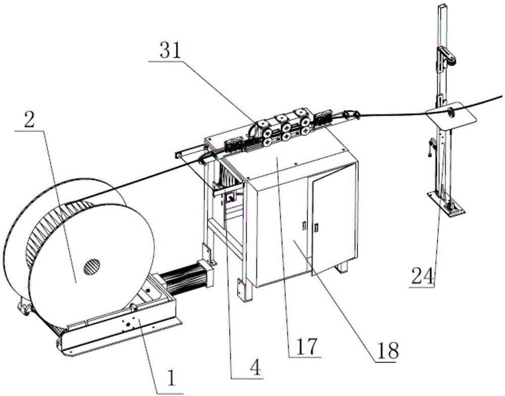
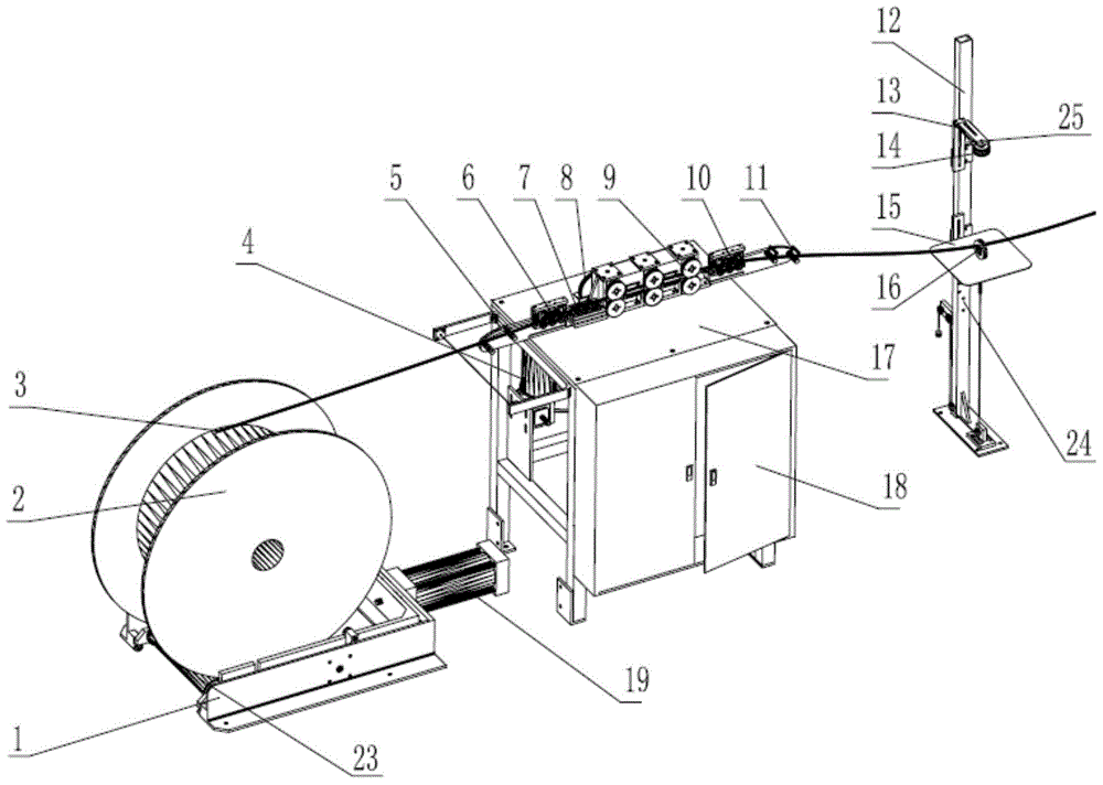
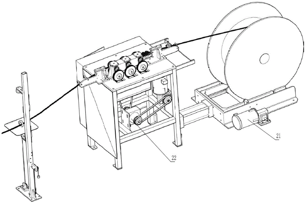
[0033] First open the pay-off reel feeding cylinder 19 on the pay-off reel frame 1, so that the pay-off reel 2 is installed on the rotating shaft 23 of the pay-off reel frame 1, then turn on the power supply, and simultaneously turn on the copper row of the pay-off reel 2 One end of 3 walks around the guide wheel 51 of the guide bracket 5 before straightening, then inserts one end of the copper bar 3 into the vertical straightening wheel A6, turns on the straightening drive motor 4, and simultaneously the pay-off motor 21 also rotates synchronously, so that the copper bar 3 After passing through the vertical straightening wheel A6, the horizontal straightening wheel 7, the straightening traction wheel 9, the vertical straightening wheel B10 and the straightening rear guide bracket 11 in turn, and passing through the middle part of the ultrasonic detection plate 15, a copper bar guide ring 16 is installed, and then The copper bar 3 is installed in the feeding mechanism of the pu...


PUM


Abstract

The invention relates to a copper bar straightening machine of a commutator. The copper bar straightening machine comprises a straightening machine frame, a straightening machine electric cabinet and a pay-off reel frame. The straightening machine frame is mounted on the upper portion of the straightening machine electric cabinet, a straightening traction component is mounted on the straightening machine frame, the pay-off reel frame is arranged on one side of the straightening machine electric cabinet while a sensing detection support is arranged on the other side of the same, a straightening drive motor is mounted in the straightening machine electric cabinet and drives a magnetic powder clutch to be connected with the straightening traction component, a pay-off motor synchronously rotating with the straightening drive motor is arranged on one side of the pay-off reel frame, a rotating shaft is longitudinally connectively arranged in the pay-off motor and the pay-off reel frame side by side, a pay-off reel is rotatably mounted on the rotating shaft, a copper bar winds the pay-off plate, and the free end of the copper bar penetrates the straightening traction component and a copper platoon guide ring on the sensing detection support in sequence. The copper bar straightening machine is simple in structure, convenient to operate and safer to operate, and pulling apart of the copper bar is avoided at the same time.

Description

technical field [0001] The invention relates to the field of copper bar straightening machine manufacturing, in particular to a commutator copper bar straightening machine. Background technique [0002] When the commutator piece is punched by a high-speed punching machine, it often occurs that the straightness of the copper bar is not good enough to cause the high-speed punching machine to feed the material not smoothly, so that the size of the produced commutator piece is not stable enough, and the feeding speed cannot keep up. The general copper bar straightening machine pulls the entire copper bar into the entire punch through the tension of the punch feed port after vertical straightening and horizontal straightening, which will break the entire copper bar due to the excessive tension of the punch. [0003] Patent No. 2012200098256 describes a simple flat copper wire straightening machine, which discloses a straightening machine, which only has a traction assembly, a ver...

Claims


Application Information

Patent Timeline
IPC IPC(8): B21D1/02B21C51/00B21F1/02B21F23/00
Inventor 郭锐孙瑞良潘荣政王耀定张光洪许刚位赵吉峰李国法
Owner HUARUI ELECTRICAL APPLIANCE
Learn More