Machining equipment for structural components of aircraft

A technology of aircraft structure and processing equipment, applied in metal processing equipment, aircraft parts, aircraft assembly and other directions, can solve the problem of high cost of downtime and achieve the effect of shortening time

Active Publication Date: 2014-11-05
布勒特耶自动控制设备有限责任公司
View PDF7 Cites 11 Cited by
  • Summary
  • Abstract
  • Description
  • Claims
  • Application Information

AI Technical Summary

Problems solved by technology

The resulting considerable downtime of the machining station, which affects to a considerable extent the cost of the aircraft structural component to be produced, is very large

Method used


Image

  • Machining equipment for structural components of aircraft
  • Machining equipment for structural components of aircraft
  • Machining equipment for structural components of aircraft

Examples


Embodiment Construction

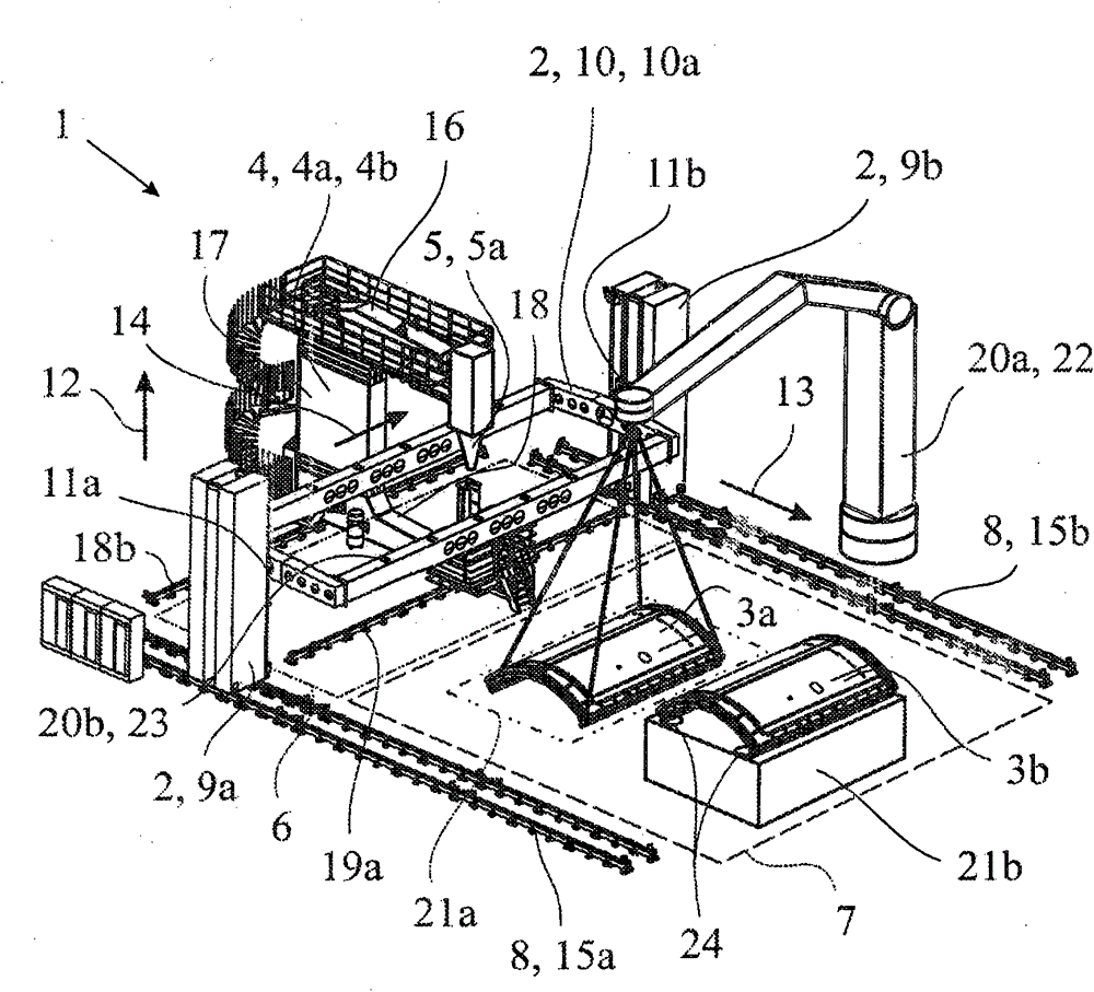
[0018] figure 1 The proposed machining plant for aircraft structural components shown in , has a machining station 1 comprising a positioning device 2 for receiving and moving aircraft structural components 3 a , 3 b and a handling machine 4 with a tool 5 .

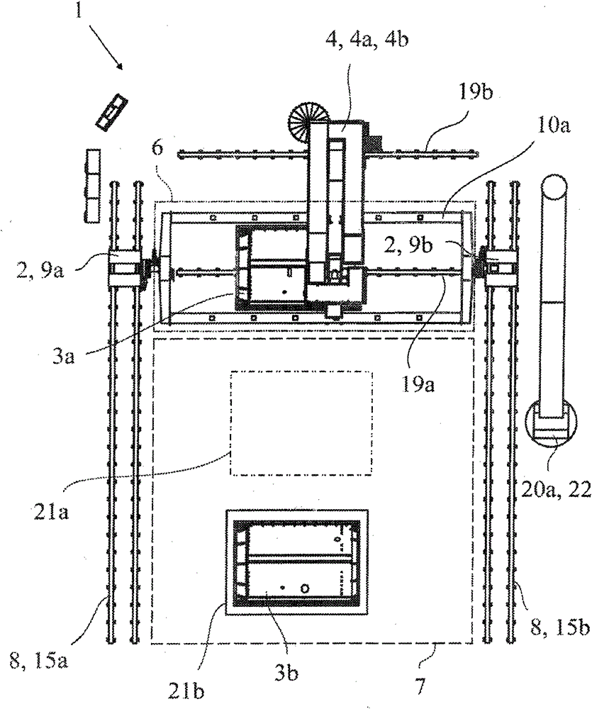
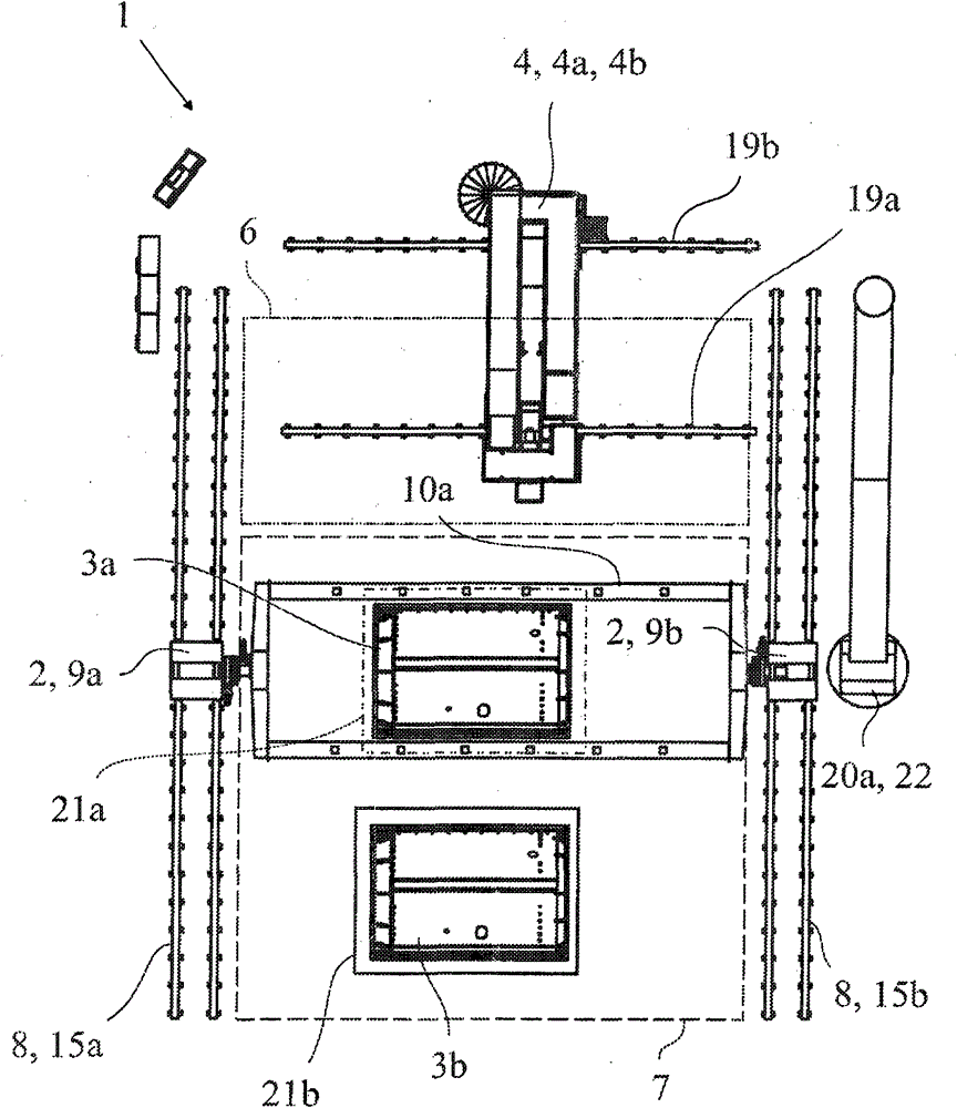
[0019] exist figure 1 In the illustration of , the positioning device 2 does not actually accommodate the aircraft structural components 3a, 3b, however, figure 2 with 5 The positioning device 2 is shown with a received aircraft structural component 3 a , 3 b in processing.

[0020] The tool 5 is here and preferably, for example, a riveter 5 a. The manipulator 4 designed to move the tool 5 according to the proposal can be understood here conceptually broadly and in the sense of robotics, ie as a movable part of any robot structure in principle. In addition to the riveting machine 5a, further tools of the same or other type may also be arranged at the manipulating machine 4 .

[0021] The movement of the aircraft str...


PUM


Abstract

The invention relates to machining equipment for structural components of an aircraft. The machining equipment is equipped with a machining station (1) which includes a locating device used for accommodating the structural components (3a, 3b) of the aircraft and enabling the structural components to move and a tool-equipped manipulator (4) of a preferably riveting machine (5a), wherein the manipulator (4) is set to enable the tool (5) to move, a working area of the machining station (1) is defined by such an area where the structural components (3a, 3b) of the aircraft accommodated by the locating device (2) can be machined through the tool (5). The machining equipment in the invention is characterized in that the machining equipment includes a loading area (7) which is separated from the working area (6) to be used for loading and/or unloading the structural components (3a, 3b) of the aircraft, and the machining equipment includes a driving device (9) which is set to enable the structural components (3a, 3b) of the aircraft which are accommodated by the locating device (2) to move particularly entirely between the working area (6) and the loading area (7). In addition, the invention relates to a method for machining the structural components of an aircraft.

Description

technical field [0001] The invention relates to a manufacturing plant for aircraft structural components with the features of the preamble of claim 1 and a method for machining aircraft structural components with the features of the preamble of claim 14 . Background technique [0002] As an important step, the automated production of aircraft and other flying objects includes the machining of fuselages, wings and other large aircraft structural components in likewise correspondingly large machining cells. In such processing cells, the aircraft structural components are usually fastened on a clamping frame, which is then moved along different degrees of freedom by means of the two positioning towers of the positioning device, while the tools, such as riveters, which are fixed on the support, are The actual machining takes place at selected points of the aircraft structural component. [0003] Such a machining cell or station is known from the recently issued patent document ...

Claims


Application Information

Patent Timeline
Patent Type & Authority Applications(China)
IPC IPC(8): B64F5/00B23Q1/25B23Q7/04B21J15/42
CPCB64F5/0009B21J15/142B23Q7/05B64F5/10
Inventor C·施泰因霍伊瑟尔M·弗尔茨V·内曼
Owner 布勒特耶自动控制设备有限责任公司
Why Eureka
Try Eureka