Light expansion shaft

A shaft-expanding, light-weight technology, which is applied in the field of expanding shafts for tightening the central reel of film-like materials, can solve the problems of requiring at least two employees, the pitch of the screw should not be too large, and the coaxiality is not easy to control, so as to achieve simple structure, Reduce the rotational inertia and solve the effect of excessive deviation of coaxiality

Inactive Publication Date: 2014-11-05
GUANGDONG SHENGYI SCI TECH
View PDF4 Cites 4 Cited by
  • Summary
  • Abstract
  • Description
  • Claims
  • Application Information

AI Technical Summary

Problems solved by technology

Among them, the key-type pneumatic expansion shaft has an inner expansion tube inside it and a plurality of protruding key strips. When in use, it is injected with air pressure, and the internal expansion tube expands outwards to push up the key strips, so that the key strips expand and tighten the membrane. The central reel of the shape material, but this kind of expansion shaft is easy to deform the outer pipe, and the coaxiality is not easy to control, and the expansion shaft except the inner expansion tube, the rest of the parts are made of metal processing, so that the entire expansion shaft It is too heavy, generally requires at least two employees to operate, and it is extremely inconvenient to use
The mechanical expansion shaft generally uses the screw to drive the conical block for expansion, but because the pitch of the screw cannot be too large, it needs to rotate many turns when expanding the central reel to meet the use requirements, and the operation time is longer and the efficiency is reduced.

Method used


Image

  • Light expansion shaft
  • Light expansion shaft

Examples


Embodiment Construction

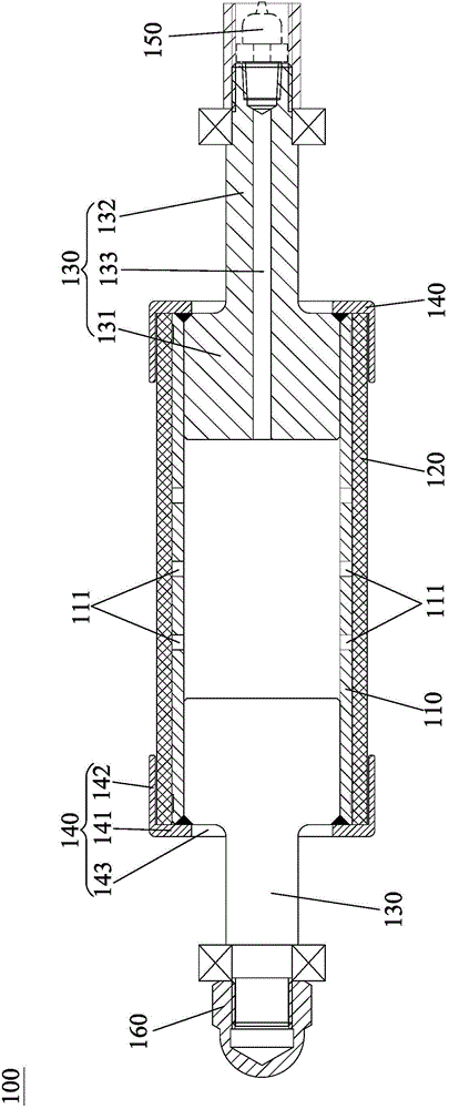
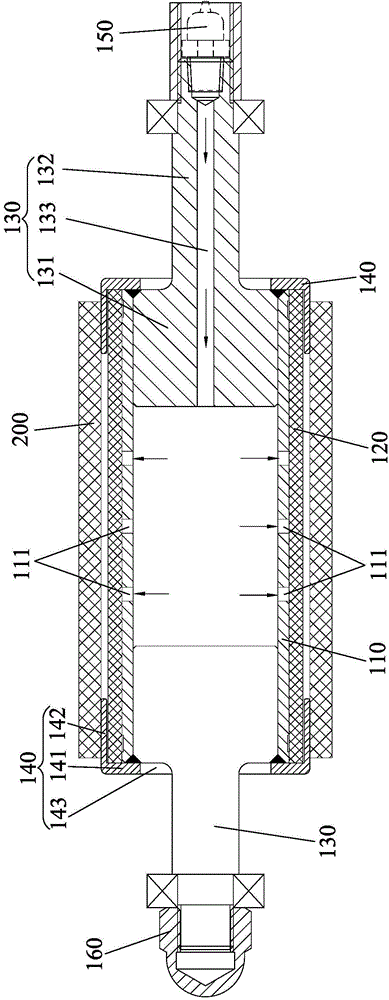
[0019] Embodiments of the present invention will now be described with reference to the drawings, in which like reference numerals represent like elements. The light-duty expansion shaft 100 provided by the present invention is suitable for winding and unwinding equipment for film-like materials, and is used for winding and unwinding the film-like materials.

[0020] Such as figure 1 , figure 2 As shown, the lightweight expansion shaft 100 provided by the present invention includes a support tube 110 and an expansion tube 120 sheathed outside the support tube 110, and the two ends of the expansion tube 120 are sealed and fixed to the support tube 110, The support tube 110 has a hollow structure and is sealed at both ends. The side wall of the support tube 110 is penetratingly provided with a vent hole 111 communicating with the hollow structure. The air intake hole 133. When in use, the central reel 200 of the film-like material is sleeved outside the expansion tube 120, a...


PUM


Abstract

The invention discloses a light expansion shaft which comprises a supporting pipe and an expansion pipe, wherein the supporting pipe is sleeved with the expansion pipe. The two ends of the expansion pipes are fixed to the supporting pipe in a sealed mode. The supporting pipe is of a hollow structure and the two ends of the supporting pipe are sealed. Vent holes communicated with the hollow structure are formed in the side wall of the supporting pipe in a penetrating mode. A gas inlet communicated with the hollow structure is further formed in the supporting pipe. When the light expansion shaft is used, the expansion pipe is sleeved with a center coiling block of a film-shaped material, pressure gas flows to the hollow structure of the supporting pipe through the gas inlet, the pressure gas enters a gap between the expansion pipe and the supporting pipe through the vent holes, so that the expansion pipe is expanded and attached to the center coiling block, the center coiling block is prevented from slipping, the expansion pipe returns to normal after the gas inside the supporting pipe is released, and the center coiling block can be conveniently taken down. The light expansion shaft is simple in structure, light in total weight, convenient to operate and capable of greatly reducing the number of operators, relieving labor intensity, improving labor efficiency and effectively solving the problem that deviation of coaxiality of the film-shaped material and the expansion shaft is too large in the prior art.

Description

technical field [0001] The invention relates to a light-duty expanding shaft, in particular to an expanding shaft used for tightening the central reel of the film-shaped material when the film-shaped material is wound and discharged in the electronics industry. Background technique [0002] A large number of film-like materials are used in the electronics industry. When winding and unwinding various film-like materials, the central reel of the film-like material must be placed on the shaft of the winding and unwinding equipment. The shaft has a certain pre-tightening force, so as to provide a winding and unwinding tension for the film material, and prevent the central roll of the film material from slipping. For this reason, the diameter of the shaft on the winding and unwinding equipment is required to be changed, so that it can expand during winding and unwinding to tighten the central reel; and it can be reduced after the completion of rewinding and unwinding. , so as to...

Claims


Application Information

Patent Timeline
IPC IPC(8): B65H16/04B65H18/04
Inventor 郭秉坚柯泳彬柳旭凯
Owner GUANGDONG SHENGYI SCI TECH
Why Eureka
Try Eureka