Self-clamping lifting device for underwater rotating body

A hoisting device and self-clamping technology, used in transportation and packaging, load hoisting components, etc., can solve hidden safety hazards, increase the difficulty of hoisting work, cumbersome and other problems, and achieve improved operational safety, convenient hoisting, reduced strength and effect of difficulty

Active Publication Date: 2016-06-08
中国船舶重工集团公司第七〇二研究所
View PDF6 Cites 0 Cited by
  • Summary
  • Abstract
  • Description
  • Claims
  • Application Information

AI Technical Summary

Problems solved by technology

The underwater glider is a streamlined underwater vehicle with a revolving body. In the past, the lifting of the underwater glider when it was launched into the sea and landed was generally carried out by conventional rings or slings. The surface is equipped with lifting rings, which not only affects the hydrodynamic performance of the aircraft, but also the operation of unhooking in the sea or landing hooks is cumbersome. Although the method of direct hoisting with slings does not need to set rings on the aircraft, it will not affect the hydrodynamic performance of the aircraft. However, the operation of untying when going to sea and strapping when going ashore is also very cumbersome, and these two hoisting forms must be carried out by operators on the sea surface with small ships to unhook, hook or unhook, etc. The operation not only increases the difficulty of hoisting work, but also has certain safety hazards due to the wide sea and high waves.

Method used


Image

  • Self-clamping lifting device for underwater rotating body
  • Self-clamping lifting device for underwater rotating body
  • Self-clamping lifting device for underwater rotating body

Examples


Embodiment Construction

[0019] The specific implementation manner of the present invention will be described below in conjunction with the accompanying drawings.

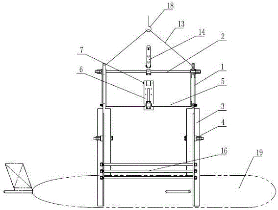
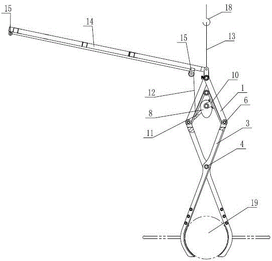
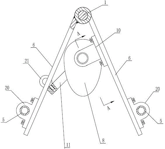
[0020] See figure 1 , figure 2 , the present invention includes two sets of unclamping mechanisms arranged in parallel along the axial direction of the steering rod 2, the unclamping mechanism includes two suspension rods 1, the upper ends of the two suspension rods 1 are axially limited and installed on the same steering rod 2 Specifically, the two suspension rods 1 are axially limited on the rod section formed by the shoulder of the steering rod 2 and the nut assembly on the steering rod 2. When the clamping operation is performed, the two suspension rods 1 can rotate around the steering rod 2. In the clamp release mechanism, the lower ends of the two suspenders 1 are respectively connected to a splint 3, and the two splints 3 are arranged crosswise. The upper end of the 3 and the lower end of the connected suspender 1 are locked on t...


PUM


Abstract

The invention discloses a self-clamping-type hoisting device for an underwater rotary body. The self-clamping-type hoisting device comprises two clamp-release mechanisms parallelly arranged along a steering rod axial direction. The clamp-release mechanism comprises two hanger rods, upper ends of the two hanger rods are installed on a steering rod, lower ends of the two hanger rods are respectively connected to two clamping plates, the two clamping plates are crosswise arranged and hinged at the intersection, and the upper ends of the clamping plates and the lower ends of the hanger rods connected to the clamping plates are locked on a connection rod. The steering rod is connected between the two clamp-release mechanisms. The parallel clamping plates of the two clamp-release mechanisms are connected to the same connection rod. Two rotary plates are respectively fixedly connected to the two connection rods. Upper ends of the two rotary plates are hinged. A cam is rotatingly supported between the two rotary plates. Through rotation of the cam, opening angles of the two rotary plates are changed, a rotation shaft of the cam is fixedly connected to one end of a pull rod, the other end of the pull rod is connected to one end of a stay cord and the other end of the stay cord is a free end. A lifting rope is connected between the two ends of the steering rod. The self-clamping-type hoisting device is convenient for hoisting operation, realizes hoisting work on shore, reduces hoisting work intensity and difficulty and improves operation safety.

Description

technical field [0001] The invention relates to the technical field of hoisting tools, in particular to a hoisting device for landing and launching an underwater revolving body. Background technique [0002] Due to the high strength and internal volume of the gyratory shell, most of the current underwater vehicles use the gyratory shell. The underwater glider is a streamlined underwater vehicle with a revolving body. In the past, the lifting of the underwater glider when it was launched into the sea and landed was generally carried out by conventional rings or slings. The surface is equipped with lifting rings, which not only affects the hydrodynamic performance of the aircraft, but also the operation of unhooking in the sea or landing hooks is cumbersome. Although the method of direct hoisting with slings does not need to set rings on the aircraft, it will not affect the hydrodynamic performance of the aircraft. However, the operation of untying when going to sea and strap...

Claims


Application Information

Patent Timeline
Patent Type & Authority Patents(China)
IPC IPC(8): B66C1/42
Inventor 朱建良冯骏张华陈鲁愚
Owner 中国船舶重工集团公司第七〇二研究所
Why Eureka
Try Eureka