
Axial turbomachine stator with ailerons at the blade roots

A technology of turbines and stators, which is applied to the supporting elements of blades, stators, mechanical equipment, etc., can solve the problems of pressure drop, reduce the flow area of ​​annular flow, etc., and achieve the effect of eliminating stall, improving performance, and improving capacity.

Active Publication Date: 2014-11-05
SAFRAN AERO BOOSTERS SA
View PDF10 Cites 2 Cited by
  • Summary
  • Abstract
  • Description
  • Claims
  • Application Information

AI Technical Summary

Problems solved by technology

The presence of multiple slats reduces the flow area of ​​the annular flow, which causes a pressure drop

Method used


Image

  • Axial turbomachine stator with ailerons at the blade roots
  • Axial turbomachine stator with ailerons at the blade roots
  • Axial turbomachine stator with ailerons at the blade roots

Examples


Embodiment Construction

[0040] In the following description, the terms inner or inner and outer or outer refer to a position relative to the axis of rotation of the axial turbine.

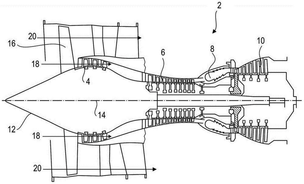
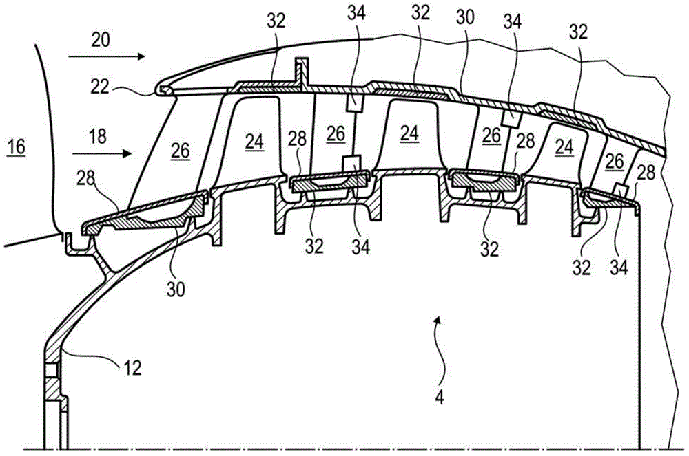
[0041] figure 1 An axial turbine is shown schematically. In this case a twin-flow turbojet. The turbojet comprises a first compression stage (the so-called low-pressure compressor 4 ), a second compression stage (the so-called high-pressure compressor 6 ), a combustion chamber 8 and one or more turbine stages 10 . In operation, the mechanical power of the turbine 10 is transmitted through the central shaft to the rotor 12 which then drives the two compressors 4 and 6 . A reduction mechanism may increase the rotational speed delivered to the compressor. Furthermore, the different turbine stages can be connected to the compressor stages by concentric shafts. The compressor stages include rows of rotor blades associated with rows of stator blades. The rotation of the rotor thus generates an air flow which is then gradu...


PUM


Abstract

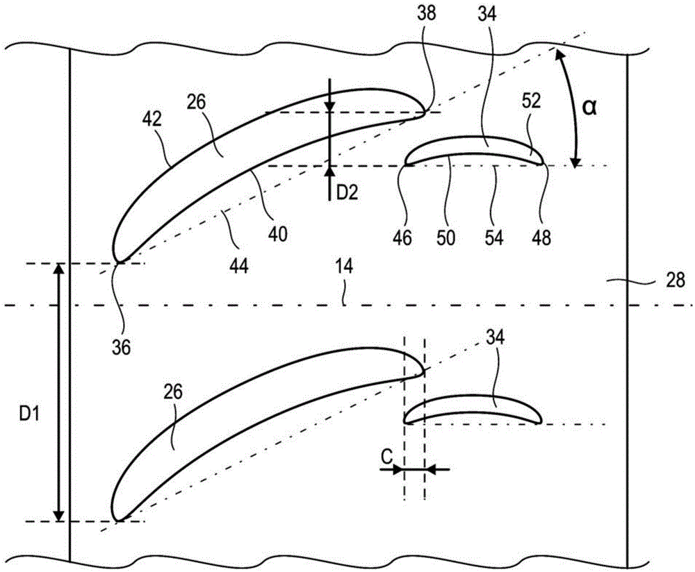
The present application relates to the compressor stator of an axial turbomachine. The stator comprises an annular row of main stator blades and auxiliary blades each of which are associated with a main blade. The auxiliary blades are located at the trailing edges of the main blades and are in the vicinity of the pressure faces of the main blades. The auxiliary blades are aligned to generate a low-pressure area at the trailing edges of the main blades. Thus, a flow bypassing a main blade by its suction face is sucked in by the low-pressure area when it approaches the trailing edge of the main blade. Stalling is thus avoided and the efficiency of the machine is improved.

Description

technical field [0001] The invention relates to a stator of an axial compressor. In particular, the invention relates to a stator of an axial turbine comprising main blades and auxiliary blades associated with the main blades. The invention also relates to an axial turbine equipped with a stator according to the invention. Background technique [0002] To straighten the annular flow, axial turbines have a stator. These blade arrays are located downstream of each annular row of rotor blades. The vanes deflect the annular flow to convert the tangential component into an axial component. This flow can then be re-accelerated by another annular array of rotor blades located downstream. [0003] The stator generally has an inner casing and an outer casing between which stator vanes extend radially. In operation, annular flow breaks away from the blades, creating entropy that reduces the efficiency of the turbine. [0004] Patent FR2939852A1 discloses a vaned stator fitted wi...

Claims


Application Information

Patent Timeline
Patent Type & Authority Applications(China)
IPC IPC(8): F01D9/00
CPCF01D9/041F04D29/681F01D5/146F01D5/145F04D29/542F04D29/544Y02T50/60F01D5/142
Inventor A.德克莱D.德佩普
Owner SAFRAN AERO BOOSTERS SA
Learn More