
Low-temperature pipe clamp

A pipe clamp, low temperature technology, applied in the direction of pipeline supports, pipes/pipe joints/pipes, mechanical equipment, etc., can solve problems such as increasing the labor cost of replacement operations, affecting the effect of pipe clamps to fix the pipeline, and increasing the cost of replacing new pipe clamps. , to achieve the effect of fast and efficient installation, shortened installation time, and simple structure

Inactive Publication Date: 2014-11-05
ZHANGJIAGANG TENGXIANG MACHINERY
View PDF7 Cites 0 Cited by
  • Summary
  • Abstract
  • Description
  • Claims
  • Application Information

AI Technical Summary

Problems solved by technology

[0004] However, the pipe clamps in the prior art usually use a cover plate and bolts to fasten the pipe clamp body. The cover plate and the pipe clamp body have sliding properties, which will directly affect the effect of the pipe clamp on fixing the pipe.
In addition, because the pipeline is affected by power machinery during work, there is generally vibration, so the contact between the pipe clamp and the pipeline will be worn due to vibration, resulting in shortened service life of the pipe clamp, which not only increases the cost of replacing the new pipe clamp but also Increased labor cost input for replacement operations

Method used


Image

  • Low-temperature pipe clamp
  • Low-temperature pipe clamp
  • Low-temperature pipe clamp

Examples


Embodiment Construction

[0024] Below in conjunction with accompanying drawing of description, the present invention will be further described.

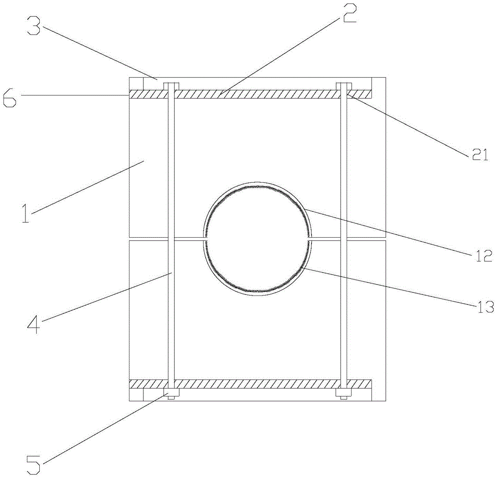
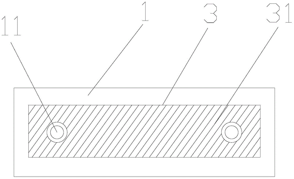
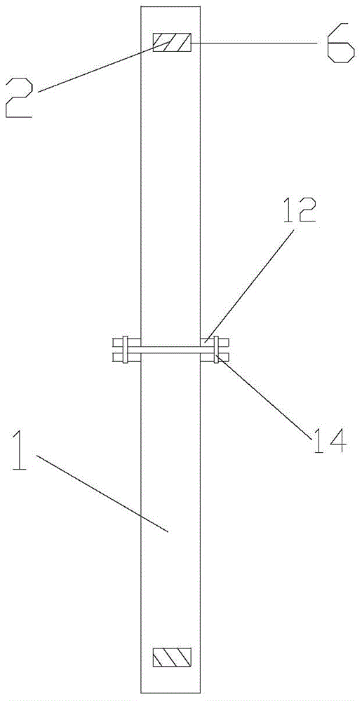
[0025] Such as figure 1 , figure 2 and image 3 as shown,

[0026] A low-temperature pipe clamp, comprising a pipe clamp body with a central through hole, the size of the central through hole matches the size of the delivery pipeline, the pipe clamp body includes two half-clamp bodies 1 with the same structure, and the half-clamp bodies One end surface of 1 is the structure of a half central through hole; the other end surface of the half clip body 1 is provided with a groove 3 for assembling the splint 2, and the splint 2 is provided with a fixing hole 21, and the two half clips The clip body 1 is fastened and connected by two bolts 4; The splint fixing hole 21 stretches out from the end of the bolt 4, and the end of the bolt 4 is locked by a nut 5; the inner wall on one side of the groove 3 is provided with a jack 6 for horizontally inserting the spli...


PUM


Abstract

The invention discloses a low-temperature pipe clamp which comprises a pipe clamp body with a central through hole, wherein the size of the central through hole is matched with the size of a conveying pipe. The pipe clamp body comprises two half clamping bodies identical in structure, one end face of each half clamping body is of a structure of half of the central through hole, the other end face of the half clamping body is provided with a groove for a clamping plate to be arranged in, a fixing hole is formed in the clamping plate, the two half clamping bodies are connected through a bolt in a fastening mode, and the tail end of the bolt is locked through a nut. An insertion hole for the clamping plate to be horizontally inserted into the groove is formed in the inner lateral wall on one side of each groove, and the size of the inserting hole is matched with the size of the thickness and the size of the width of the clamping plate. The low-temperature pipe clamp is simple in structure, convenient to operate and good in steady effect, tight connection of the clamping plate is improved, sliding of the clamping plate in the installation process is eliminated, abrasion resistance of the pipe clamp is improved, service life of the pipe clamp is prolonged, and replacement cost is reduced. Furthermore, the clamping plate serving as the part can be preinstalled in a factory-like mode, labor time on installation on site is shortened, and cost is reduced further.

Description

technical field [0001] The invention relates to a pipe clip, in particular to a low-temperature pipe clip. Background technique [0002] The pipe clamp is a pipe clamp suitable for fixing pipelines with oil, water and gas as the medium. Generally used in metallurgy, mining, chemical industry, coal, heavy machinery, construction machinery, shipbuilding, textile and agricultural machinery and other industries. [0003] Generally, the pipeline is mainly made of steel pipes. In order to ensure the fixed strength, the pipe clamps used in the pipeline are usually made of metal or plastic; the fixing method is generally a single independent pipe clamp, and these pipe clamps guarantee the strength and stability of the pipeline to a certain extent stability. [0004] However, the pipe clamps in the prior art usually use a cover plate and bolts to fasten the pipe clamp body, and there is sliding between the cover plate and the pipe clamp body, which will directly affect the effect o...

Claims


Application Information

Patent Timeline
Patent Type & Authority Applications(China)
IPC IPC(8): F16L3/10
CPCF16L3/1091
Inventor 陈跃松
Owner ZHANGJIAGANG TENGXIANG MACHINERY
Learn More