Supercharge Your Innovation With Domain-Expert AI Agents!

A device for measuring root-soil friction force

A measuring device and friction force technology, which is applied in the field of root-soil root system friction measuring devices, can solve the problems of inaccurate recording of experimental data, large human interference factors, etc., and achieve simple and flexible measuring devices, increased accuracy, and strong operability Effect

Inactive Publication Date: 2016-06-29
KUNMING UNIV OF SCI & TECH
View PDF2 Cites 0 Cited by
  • Summary
  • Abstract
  • Description
  • Claims
  • Application Information

AI Technical Summary

Problems solved by technology

However, the existing friction measurement devices generally adopt the direct measurement method of the tension meter, and the human interference factors are relatively large, and the experimental data cannot be accurately recorded, which will cause a large measurement error. Therefore, it is necessary to provide a root-soil root system friction measurement device. to make up for these shortcomings

Method used


Image

  • A device for measuring root-soil friction force
  • A device for measuring root-soil friction force
  • A device for measuring root-soil friction force

Examples


Embodiment 1

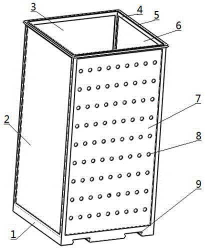
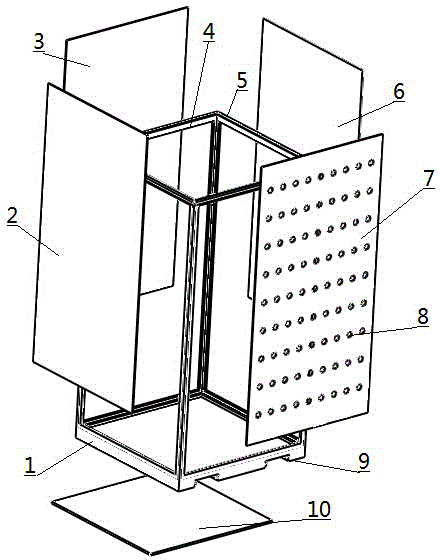
[0018] Embodiment 1: as Figure 1-6 As shown, a root-soil root system friction measuring device includes a root system burying device and a measuring device; the root system burying device includes a frame base 1, a left baffle 2, a rear baffle 3, a card slot 4, a handle 5, and a right baffle 6. Front baffle 7, root hole 8, slide rail groove 9 and bottom baffle 10; slide rail groove 9 is provided at the bottom of the frame base 1, and card slots 4 are respectively provided on the front, rear, left, and right sides of the root system burying device for inserting stoppers. When in use, the baffle is inserted into the card slot 4 from top to bottom perpendicular to the bottom. The baffle is mainly divided into a left baffle 2, a rear baffle 3, a right baffle 6 and a front baffle 7, wherein the front baffle 7 consists of Root system holes 8 are arranged in equal rows from top to bottom, and the number of holes in each row on the front baffle 7 is equal and distributed at equal int...

Embodiment 2

[0021] Embodiment 2: as Figure 1-6 As shown, a root-soil root system friction measuring device includes a root system burying device and a measuring device; the root system burying device includes a frame base 1, a left baffle 2, a rear baffle 3, a card slot 4, a handle 5, and a right baffle 6. Front baffle 7, root hole 8, slide rail groove 9 and bottom baffle 10; slide rail groove 9 is provided at the bottom of the frame base 1, and card slots 4 are respectively provided on the front, rear, left, and right sides of the root system burying device for inserting stoppers. When in use, the baffle is inserted into the card slot 4 from top to bottom perpendicular to the bottom. The baffle is mainly divided into a left baffle 2, a rear baffle 3, a right baffle 6 and a front baffle 7, wherein the front baffle 7 consists of Root system holes 8 are arranged in equal rows from top to bottom, and the number of holes in each row on the front baffle 7 is equal and distributed at equal int...


PUM


Abstract

The invention relates to a rhizosphere-soil root friction measuring apparatus, and belongs to the technical field of measuring plant root friction. The apparatus comprises a root burying device and a measuring device; the root burying device comprises a frame pedestal, a left baffle, a rear baffle, a clamping groove, a handle, a right baffle, a front baffle, a root hole, a slide-rail groove and a bottom baffle; and the measuring device comprises a left positioning slide block, a left set screw, a left belt-trough slide rail, a right positioning slide block, a right set screw, a right belt-trough slide rail, a right support slide arm, a right positioning screw, a left support slide arm, a left positioning screw, a screw rod, a ring sleeve, a rolling ball I, a support, a rocker, a gear II, a gear I, a ball II, a connecting shaft, a tension sensor, an external wiring end, a sleeve, a clamp holder, a clamping screw and a positioning plate. The apparatus is applied to plant rhizosphere-soil root friction characteristic experiments, is capable of dynamically measuring root friction at different soil layers, and is easy to install, high in operationality, simple and flexible.

Description

technical field [0001] The invention relates to a root-soil root system friction measurement device, which belongs to the technical field of plant root system friction measurement. Background technique [0002] Plant roots have a good soil-fixing effect. In recent years, with the development of soil and water conservation technology, research on plant roots has become more in-depth, and the measurement of root friction is also particularly important. However, the existing friction measurement devices generally adopt the direct measurement method of the tension meter, and the human interference factors are relatively large, and the experimental data cannot be accurately recorded, which will cause a large measurement error. Therefore, it is necessary to provide a root-soil root system friction measurement device. to make up for these shortcomings. Contents of the invention [0003] The technical problem to be solved by the present invention is: the present invention provide...

Claims


Application Information

Patent Timeline
Patent Type & Authority Patents(China)
IPC IPC(8): G01N19/02
Inventor 张云伟陈岭王大龙喻勇樊阳阳武占曾详义
Owner KUNMING UNIV OF SCI & TECH
Features
  • R&D
  • Intellectual Property
  • Life Sciences
  • Materials
  • Tech Scout
  • Unparalleled Data Quality
  • Higher Quality Content
  • 60% Fewer Hallucinations
Learn More