Image defogging method and system

An image and image area technology, applied in the field of image defogging methods and systems, can solve problems such as halo effect

Inactive Publication Date: 2014-11-05
SHENZHEN INST OF ADVANCED TECH CHINESE ACAD OF SCI
View PDF2 Cites 8 Cited by
  • Summary
  • Abstract
  • Description
  • Claims
  • Application Information

AI Technical Summary

Problems solved by technology

[0006] Based on this, it is necessary to provide an image defogging method and system for the problem that the current dark c

Method used


Image

  • Image defogging method and system
  • Image defogging method and system
  • Image defogging method and system

Examples


Embodiment Construction

[0022] In order to make the object, technical solution and advantages of the present invention clearer, the present invention will be further described in detail below in conjunction with the accompanying drawings and embodiments. It should be understood that the specific embodiments described here are only used to explain the present invention, not to limit the present invention.

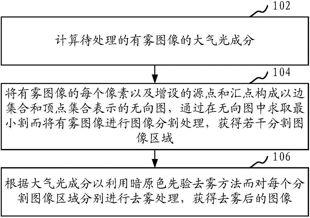
[0023] Here, the principle of the dark channel prior defogging method is explained first. In computer vision and computer graphics, a foggy image can be represented by formula (1):

[0024] I(x)=J(x)t(x)+A[1-t(x)] formula (1)

[0025] Among them, x represents a certain pixel; I(x) refers to the observed image intensity of the input foggy image, indicating a foggy image; J(x) refers to the light intensity of the scene without fog, Represents the image after defogging; A is the external atmospheric light component, which can be processed as a constant vector; t(x) refers to the part of the light th...


PUM


Abstract

The invention provides an image defogging method, which comprises the following steps: calculating the atmospheric light component of a foggy image to be processed; constructing each pixel of the foggy image and added source points and focal points into an undirected graph represented by an edge set and a vertex set, and solving a minimum cut in the undirected graph to carry out image segmentation processing to the foggy image so as to obtain a plurality of segmented image areas; and according to the atmospheric light component, independently carrying out defogging processing to each segmented image area by adopting a dark channel prior defogging method to obtain a defogged image. Firstly, the foggy image is subjected to the image segmentation processing by adopting an image segmentation method based on image segmentation to obtain a plurality of segmented image areas, then, each segmented image area is subjected to the defogging processing independently by adopting the dark channel prior defogging method, so that the obtained defogged image avoids from generating an obvious halo effect defect on an edge, and the obtained defogged image is clear and undistorted. The invention also provides an image defogging system.

Description

technical field [0001] The present invention relates to the technical field of image processing, in particular to an image defogging method and system. Background technique [0002] In foggy climates, due to the large number of particles such as water droplets in the atmosphere, as the distance between the object and the imaging device increases, the impact of the scattering of atmospheric particles on imaging gradually increases. This impact is mainly caused by two scattering processes: the first First, the reflected light on the surface of the object is attenuated due to the scattering of atmospheric particles when it reaches the imaging device; second, natural light enters the imaging device to participate in imaging due to the scattering of atmospheric particles. Their combined effects lead to low contrast, low saturation and hue shift in the captured image, which not only affects the visual effect of the image, but also affects the performance of image analysis and unde...

Claims


Application Information

Patent Timeline
IPC IPC(8): G06T5/00G06T7/00
Inventor 朱青松吴迪王磊
Owner SHENZHEN INST OF ADVANCED TECH CHINESE ACAD OF SCI
Why Eureka
Try Eureka