Method and system for reducing localized artifacts in imaging data

A technique of imaging data, local, applied in image data processing, instruments for radiological diagnosis, reconstruction from projection, etc.

Active Publication Date: 2014-11-05
KONINKLJIJKE PHILIPS NV
View PDF5 Cites 19 Cited by
  • Summary
  • Abstract
  • Description
  • Claims
  • Application Information

AI Technical Summary

Problems solved by technology

However, involuntary patient movements such as cardiac motion, respiration ...

Method used


Image

  • Method and system for reducing localized artifacts in imaging data
  • Method and system for reducing localized artifacts in imaging data
  • Method and system for reducing localized artifacts in imaging data

Examples


Embodiment Construction

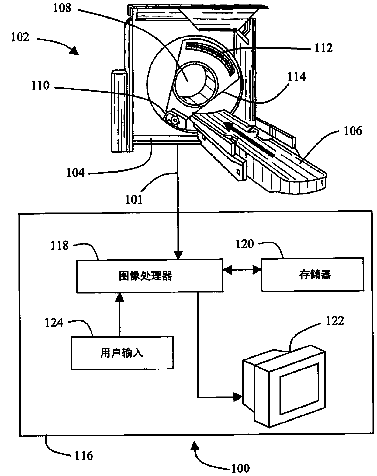
[0014] The disclosed subject matter is used in conjunction with any imaging system that involves motion artifacts, such as a CT imaging system. More specifically, refer to figure 1 , in one embodiment the imaging system 100 is a medical CT imaging system. The CT imaging acquisition system 102 includes a gantry 104 and a subject support 106 such as a table or couch that moves along the z-axis. A patient or other subject to be imaged (not shown) lies or is placed on subject support 106 and moved to be disposed within aperture 108 in gantry 104 . Once the patient or subject is in position within the aperture 108 , an X-ray source 110 emits projections of X-rays to be collected by an X-ray data measurement system 112 inside the gantry 104 . (exist figure 1 A portion 114 of the frame 104 is cut away to show the X-ray source 110 and the X-ray data measurement system 112 housed inside the frame 104). X-ray source 110 and data measurement system 112 rotate together about aperture ...


PUM


Abstract

A method and system for reducing localized artifacts in imaging data, such as motion artifacts and bone streak artifacts, are provided. The method includes segmenting the imaging data to identify one or more suspect regions in the imaging data near which localized artifacts are expected to occur, defining an artifact-containing region of interest in the imaging data around each suspect region, and applying a local bias field within the artifact-containing regions to correct for the localized artifacts.

Description

technical field [0001] The present application relates generally to the field of imaging, and more particularly to a method and system for reducing motion artifacts in medical x-ray computed tomography (CT) imaging. The subject matter of the present application also finds application in other imaging systems involving motion artifacts, for example also in general radiography (GR), magnetic resonance imaging (MR), nuclear medicine (NM), and combinations thereof. Nuclear medicine includes, for example, single photon emission computed tomography (SPECT) imaging systems and positron emission tomography (PET) imaging systems. [0002] In its broader aspects, however, the subject matter of the present application is not limited to the field of medical imaging, and may be applicable to imaging systems in non-medical fields. These imaging systems typically collect imaging data about subjects, such as humans, and record the imaging data for subsequent analysis and use. Such uses incl...

Claims


Application Information

Patent Timeline
IPC IPC(8): A61B6/00A61B6/03G06T5/00G06T7/00
CPCA61B6/5211A61B6/5258A61B6/032G06T5/005G06T11/005G06T7/0081G06T2207/10081G06T7/11G06T7/246G06T7/187G16H50/20G06F18/22G06F18/24A61B6/46A61B6/5264G06T5/00G06T7/0012G06T11/008G06T2207/20182G06T2207/20201G06T2207/30008
Inventor A·A·伊索拉E·S·汉西斯J·维格特
Owner KONINKLJIJKE PHILIPS NV
Why Eureka
Try Eureka