Bead ring winding device

A technology of a coiling device and a bead ring, which is applied to tires, rings made from wires, and other household appliances, etc., can solve the problem of inability to coil a tapered bead ring.

Active Publication Date: 2014-11-05
THE YOKOHAMA RUBBER CO LTD
View PDF4 Cites 4 Cited by
  • Summary
  • Abstract
  • Description
  • Claims
  • Application Information

AI Technical Summary

Problems solved by technology

[0004] However, in the configuration of Patent Document 1, the bottom surface of the concave portion of the bead winder is parallel to the axis of the bead winder, and it is not possible to wind a tapered bead.

Method used


Image

  • Bead ring winding device
  • Bead ring winding device
  • Bead ring winding device

Examples


Embodiment Construction

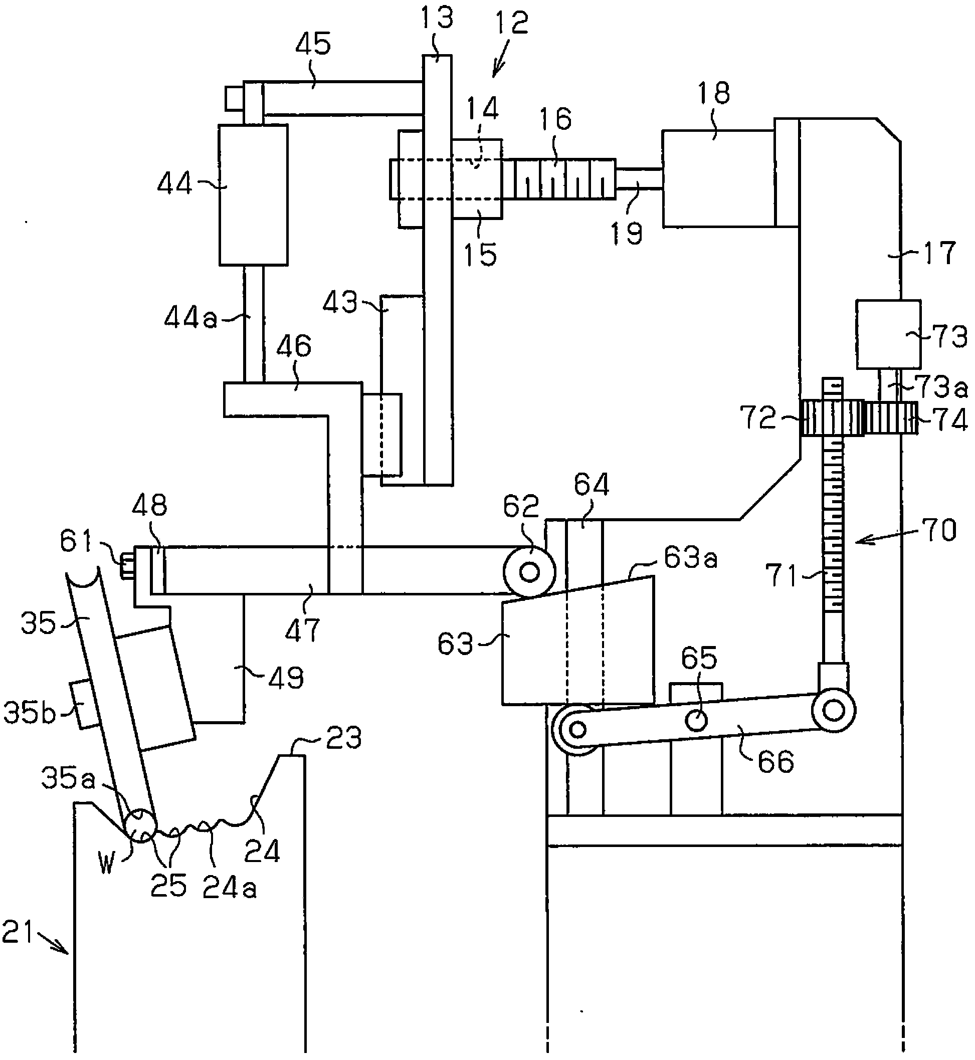
[0024] The following follows Figure 1 to Figure 5 One embodiment of a traveler winding device embodying the present invention will be described.

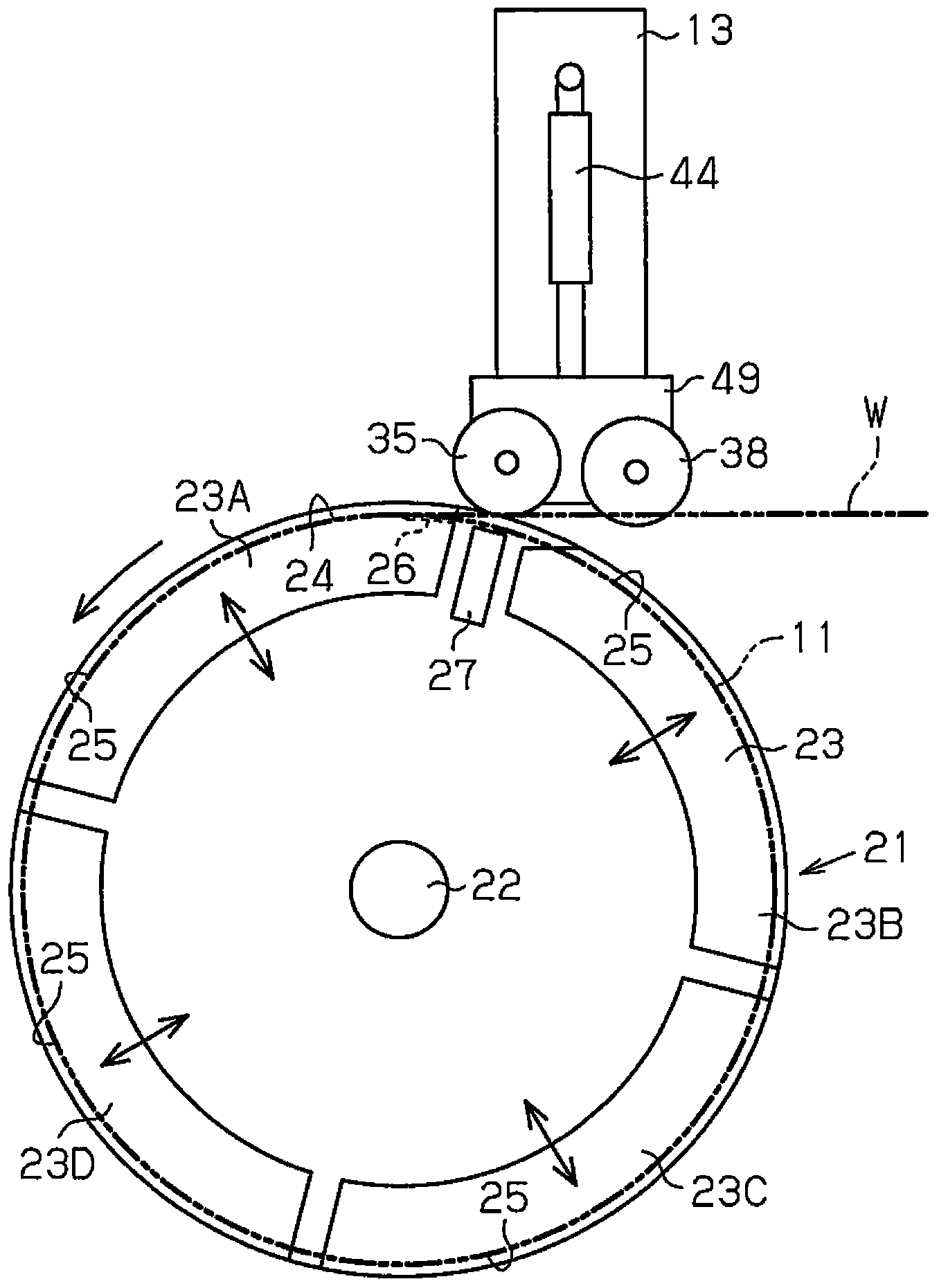
[0025] Such as figure 2 As shown, the rotating body 21 is supported on the frame 17 of the winding device in a manner capable of rotating about a rotating shaft (horizontal shaft) 22 (see figure 1 )superior. An annular winding portion 23 for winding the wire W is provided on the outer peripheral surface of the rotating body 21 . The winding portion 23 is divided in the circumferential direction. The take-up unit 23 is constituted by a plurality of divided bodies 23A to 23D supported so as to be movable in the radial direction of the rotating body 21 . The wire W is formed by covering the outer peripheral surface of the wire with a coating such as rubber.

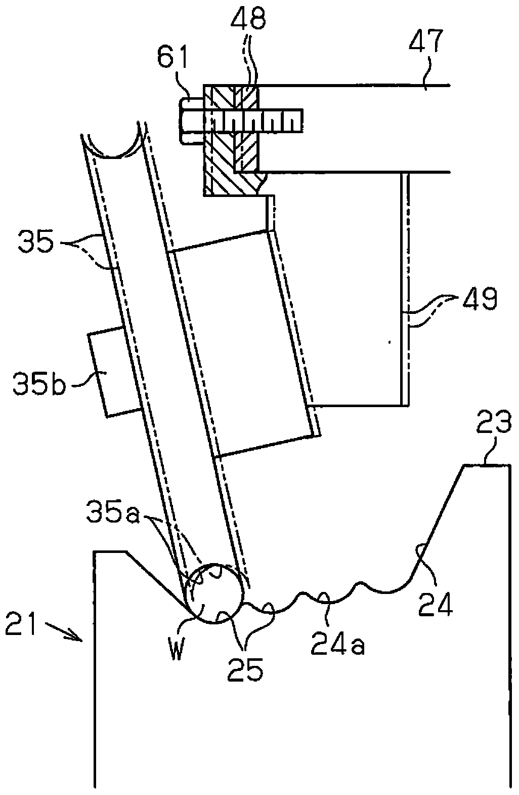
[0026] Such as figure 1 as well as figure 2 As shown, on the outer peripheral surface of each of the divided bodies 23A to 23D, in order to form the traveler 11 by windi...


PUM


Abstract

A bead ring winding device is provided with a traverse mechanism (12) comprising: a rotating body (21); a traverse roller (35); and an air cylinder (44). The rotating body (21) is provided so as to be capable of rotating about a rotation shaft and has an outer peripheral surface on which an annular winding section (23) for winding a wire is formed. The traverse roller (35) engages with the wire (W) wound by the winding section (23) and arranges the windings of the wire (W) side by side in the direction of extension of the rotation shaft. The air cylinder (44) applies pressing force to the traverse roller (35) in the direction in which the traverse roller (35) presses the wire (W). The bottom surface of the winding section (23) is formed in a tapered shape. The traverse mechanism (12) is provided with a cam member (63) having a sloped cam surface (63a). The sloped cam surface (63a) guides the traverse roller (35) so that the traverse roller (35) traverses parallel to the tapered surface (24a) of the winding section (23).

Description

technical field [0001] The present invention relates to a bead winding device used in vehicle tires and the like to wind a metal wire to form a bead. Background technique [0002] Conventionally, as such a traveler winding machine, for example, a configuration disclosed in Patent Document 1 has been proposed. In such a conventional configuration, an annular concave portion is formed on the outer peripheral surface of the traveler winder rotatable around the shaft, and the concave portion is used to wind the wire into multiple rows and multiple stages. [0003] In one embodiment described in Patent Document 1, a pitch feed roller is disposed above the bead winding machine, and the pitch feed roller is rotatably supported by a support portion. The supporting portion is supported by guide members such as rails, and is configured to be movable in a direction perpendicular to the feeding direction of the wire. The pitch feed rollers move pitch by pitch (thickness of the wire) i...

Claims


Application Information

Patent Timeline
Patent Type & Authority Applications(China)
IPC IPC(8): B29D30/48B21F37/00
CPCB29D30/48B29D2030/487B21F37/00
Inventor 西田喜八郎
Owner THE YOKOHAMA RUBBER CO LTD
Why Eureka
Try Eureka