
Spectral imaging

An imaging system and spectral characteristic technology, which is applied in the fields of spectral diagnosis, instrumentation, X/γ/cosmic radiation measurement, etc., can solve the problems of image quality reduction and noise in volumetric image data

Active Publication Date: 2014-11-05
KONINKLJIJKE PHILIPS NV
View PDF4 Cites 3 Cited by
  • Summary
  • Abstract
  • Description
  • Claims
  • Application Information

AI Technical Summary

Problems solved by technology

However, for larger objects, few 80kVp photons pass through the object, and the volumetric image data may be noisy and have reduced image quality

Method used


Image

  • Spectral imaging
  • Spectral imaging
  • Spectral imaging

Examples


Embodiment Construction

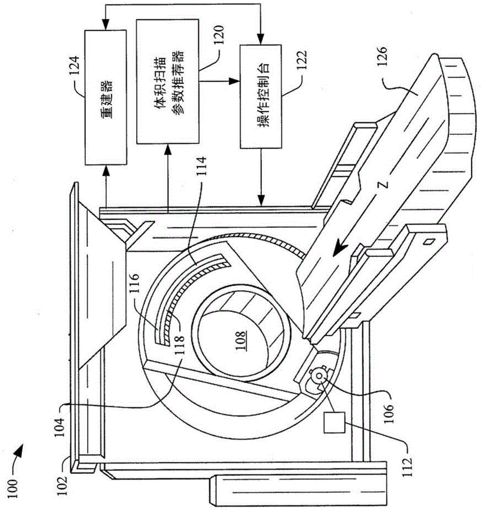
[0017] figure 1 An imaging system 100 such as a computed tomography (CT) scanner 100 is schematically illustrated. Imaging system 100 includes a stationary gantry 102 and a rotating gantry 104 . The rotating frame 104 is rotatably supported by the fixed frame 102 . The rotating gantry 104 is configured to rotate about an examination region 108 about a longitudinal or z-axis.

[0018] At least one radiation source 106, such as an X-ray tube, is supported by the rotating gantry 104 and rotates therewith. For example, for a 2D projection scan, the rotating gantry 104 is rotated to move the radiation source 106 to a predetermined static angular position if not already there. For volumetric scanning, the rotating gantry 104 is also rotated to rotate the radiation source 106 around the examination region 108 .

[0019] The radiation source voltage determiner 112 is configured to switch the peak emission voltage between two or more voltages (eg, 80 kVp, 100 kVp, 140 kVp, etc.) fo...


PUM


Abstract

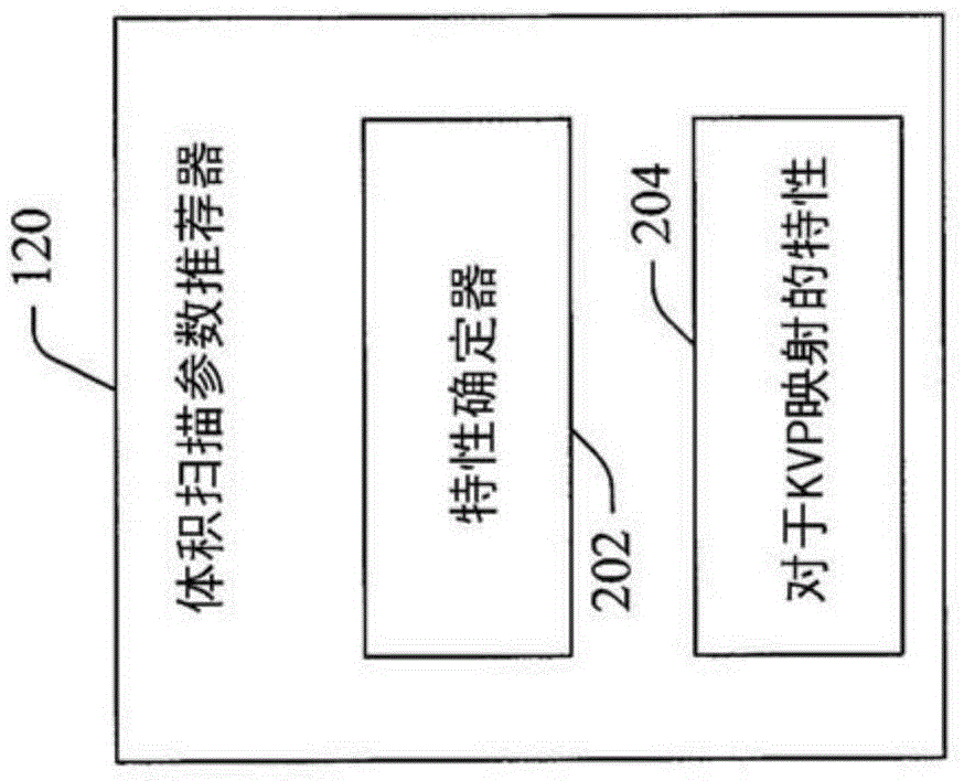
An imaging system includes radiation source (106) that emits radiation that traverses an examination region and a portion of a subject therein and a detector array (114) that detects radiation that traverses the examination region and the portion of the subject therein and generates a signal indicative thereof. A volume scan parameter recommender (120) recommends at least one spectral scan parameter value for a volume scan of the portion of the subject based on a spectral decomposition of first and second 2D projections acquired by the radiation source and detector array. The first and second 2D projections have different spectral characteristics. A console (122) employs the recommended at least one spectral scan parameter value to perform the volume scan of the portion of the subject.

Description

technical field [0001] The following generally relates to spectral imaging, and more specifically to determining the spectral peak value for a spectrum based on two or more two-dimensional (2D) projection scans (scanned images) performed at two or more kVp from approximately the same acquisition viewing angle. Appropriate tube voltages for plethysmography, and are described below in connection with specific applications to computed tomography (CT). Background technique [0002] Conventional CT scanners typically include an x-ray tube mounted on a rotatable gantry opposite a detector array across the examination region. The rotatable gantry and thus the X-ray tube rotates around the examination area. The x-ray tube emits radiation that is detected by the detector array through the examination region and parts of the object therein. The detector array generates and outputs a signal indicative of the scanned portion of the object. The signal is reconstructed to generate thre...

Claims


Application Information

Patent Timeline
Patent Type & Authority Applications(China)
IPC IPC(8): G01T1/29
CPCG01T1/2008G01T1/2985A61B5/0075A61B6/42A61B6/5205
Inventor D·舍费尔A·特伦T·克勒
Owner KONINKLJIJKE PHILIPS NV
Learn More