
Space-time resolved spectral imaging system

A spectral imaging and space-time resolution technology, applied in the field of spectral imaging, can solve problems such as low sampling throughput, system mechanical error direction change interference, inability to accurately measure spectral data, etc., to achieve improved spatial resolution, improved functions and performance, Overcome the effect of low sampling throughput

Active Publication Date: 2018-02-23
NANJING UNIV
View PDF7 Cites 2 Cited by
  • Summary
  • Abstract
  • Description
  • Claims
  • Application Information

AI Technical Summary

Problems solved by technology

These two dark-field microscopes have their own advantages and disadvantages. For example, the spectral detection type dark-field microscope can stably collect the scattering spectrum of single-particle nanoparticles, but it needs to collect the spectra of nanoparticles one by one, and cannot perform spectra of multiple particles at the same time. Acquisition, the sampling throughput is low, and there is a strong scattering background in the biological system, which affects the detection sensitivity
The scattered light intensity dark field microscope avoids the interference of biological background scattering, and has extremely high time resolution and sensitivity. However, since it detects the scattered light intensity of the target sample at this wavelength, it is vulnerable to fluctuations in the light intensity of the light source. The interference caused by mechanical errors and changes in the direction of the asymmetric target sample makes it impossible to accurately measure its spectral data

Method used


Image

  • Space-time resolved spectral imaging system
  • Space-time resolved spectral imaging system
  • Space-time resolved spectral imaging system

Examples


Embodiment 1

[0042] Such as figure 1 , a space-time resolved spectral imaging system, including a pulsed laser light source system, a microscope system, an imaging module and an image processing module;

[0043] The emission wavelength of the pulsed laser light source system is at λ 1 and lambda 2 pulsed laser beams alternating between;

[0044] The microscope system and imaging module are arranged on the output optical path of the pulsed laser light source system;

[0045] The image processing module extracts the picture obtained by the imaging module, and obtains a picture representing the local surface plasmon resonance wavelength of the target sample by performing calculation processing on the scattered light intensity of the picture, so as to realize time-space resolution spectral imaging.

Embodiment 2

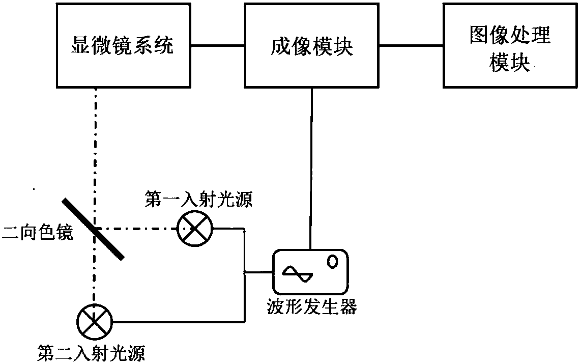
[0047] Such as figure 2 , a space-time resolved spectral imaging system, including a waveform generator, a pulsed laser light source system, a microscope system, an imaging module, and an image processing module;

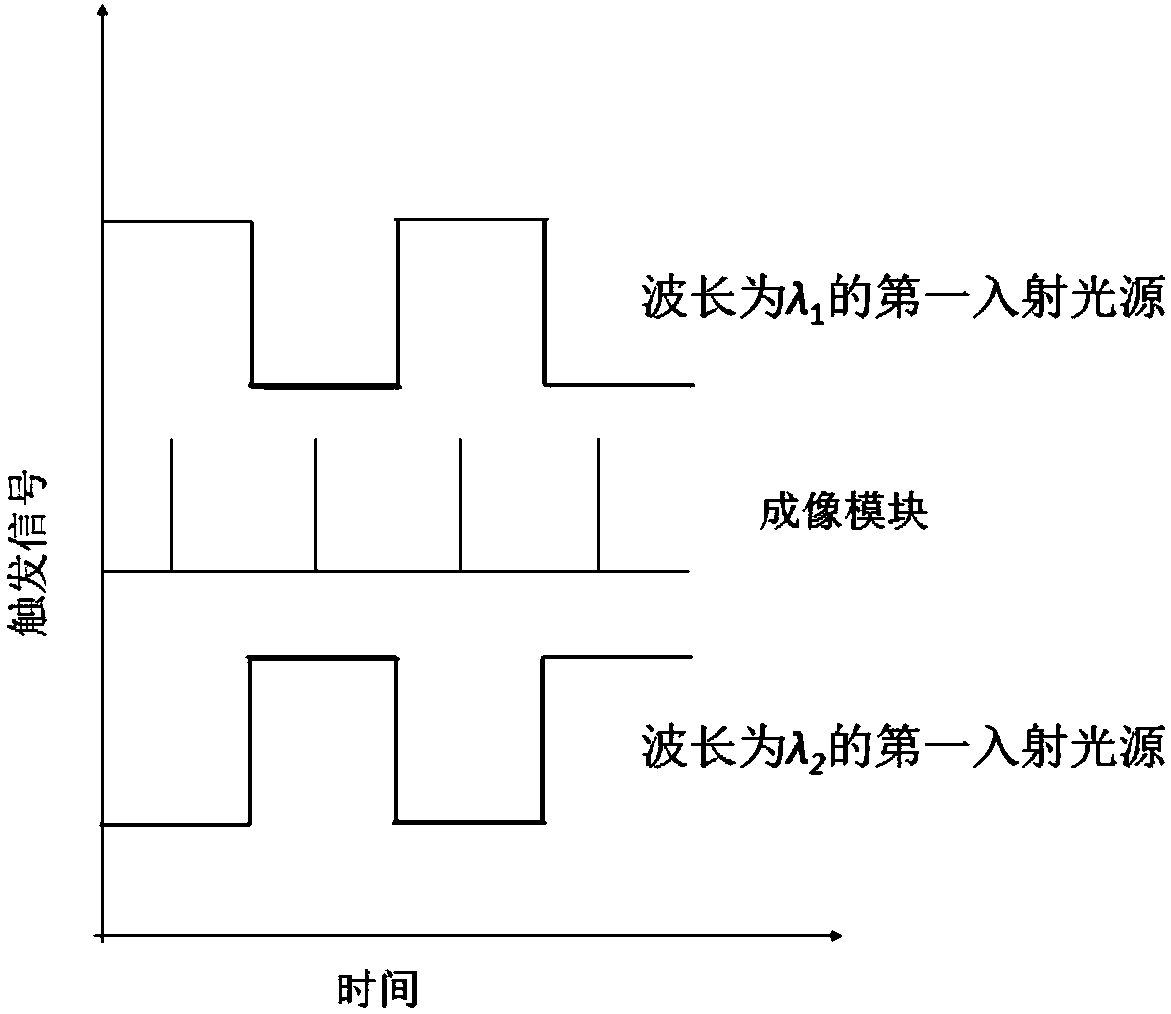
[0048] The laser light source system includes a wavelength of λ 1 The first incident light source with a wavelength of λ 2 The second incident light source and the dichroic mirror, the incident light of the first incident light source is reflected by the dichroic mirror and the incident light of the second incident light source passing through the dichroic mirror converges into a bundle of wavelengths at λ 1 and lambda 2 Pulse beams alternating between;

[0049] The waveform generator is connected to the first incident light source, the second incident light source and the imaging module; the waveform generator outputs three different trigger signals to the first incident light source, the second incident light source and the imaging module simultaneously; The tr...

Embodiment 3

[0064] Same as Embodiment 1 or 2, the difference is that the microscope system of the space-time resolution spectral imaging system adopts a total internal reflection microscope, a transmission dark field microscope, a reflection dark field microscope, a light sheet microscope, a confocal microscope or an endoscope.

[0065] Spatial-temporal resolution spectral imaging system based on total internal reflection microscopy such as image 3 , the pulsed beam passes through an oil lens with a high numerical aperture, and irradiates the sample stage at a high angle greater than 70°; generates a highly inclined and laminated optical sheet (HILO for short); irradiates nanoparticles with HILO to generate a local surface Plasmon resonance scattering, the scattered light signal is collected by the oil lens, and enters the imaging module for dark field scattering imaging.

[0066] In order to obtain two beams of light with parallel polarization directions, a polarizer can be arranged bet...


PUM


Abstract

The invention belongs to the technical field of an optical micro-instrument manufacturing technology and a spectral imaging technology and particularly relates to a space-time resolved spectral imaging system. The system comprises a pulsed laser light source system, a microscope system, an imaging module and an image processing module. The pulsed laser light source system emits pulsed laser lightbeams with wavelengths lambda 1 and lambda 2 changed alternately. The microscope system and the imaging module are arranged on an output light path of the pulsed laser light source system. The image processing module extracts images of the imaging module. Through calculating processing on image scattering light intensity, images of resonance wavelength of plasmas on the local surface of a target sample are acquired and space-time resolved spectral imaging is realized. The space-time resolved spectral imaging system can simultaneously detect resonance scattering wavelength of plasmas on the local surfaces of the multiple target samples, reduce spectrum temporal resolution to the millisecond level from the second level and significantly improve the spatial resolution.

Description

technical field [0001] The invention belongs to the field of optical micro-instrument manufacturing technology and spectral imaging technology, in particular to a time-space resolution spectral imaging system. Background technique [0002] Metallic or semiconducting nanomaterials have received extensive attention due to their stable localized surface plasmon scattering properties. In order to take advantage of the ultrasensitive response of scattered light to the refractive index of nanomaterial surfaces, a variety of dark-field microscopes have been developed to study the application of plasmonic nanoprobes in chemical and biological analysis. There are two main types of dark field microscopes available at present: spectral detection type and scattered light intensity detection type. The spectral detection type dark-field microscope uses a broadband light source and a spectrometer to analyze the plasmon resonance scattering spectrum, while the scattered light intensity typ...

Claims


Application Information

Patent Timeline
IPC IPC(8): G01N21/552
CPCG01N21/554G01N2201/12G01N2201/061
Inventor 陈子轩朱俊杰
Owner NANJING UNIV
Learn More