Cameras with Varying Spatio-Angular-Temporal Resolutions

a technology of spatio-angular-temporal resolution and cameras, applied in the field of cameras and computational photography, can solve the problems of high bandwidth, inability to achieve single lens, high-speed cameras are expensive,

Inactive Publication Date: 2010-01-07
MITSUBISHI ELECTRIC RES LAB INC
View PDF19 Cites 55 Cited by
  • Summary
  • Abstract
  • Description
  • Claims
  • Application Information

AI Technical Summary

Benefits of technology

[0020]By exploiting redundancy in light samples, the invention provides a programmable trade-off in resolution among spatial, angular and temporal dimensions. This enables a user to select an appropriate spatial,

Problems solved by technology

An array of attenuating layers in a lenslet can provide split field of view, which cannot be achieved with a single lens.
However, high speed cameras are expensive, and require a high bandwidth

Method used


Image

  • Cameras with Varying Spatio-Angular-Temporal Resolutions
  • Cameras with Varying Spatio-Angular-Temporal Resolutions
  • Cameras with Varying Spatio-Angular-Temporal Resolutions

Examples


Embodiment Construction

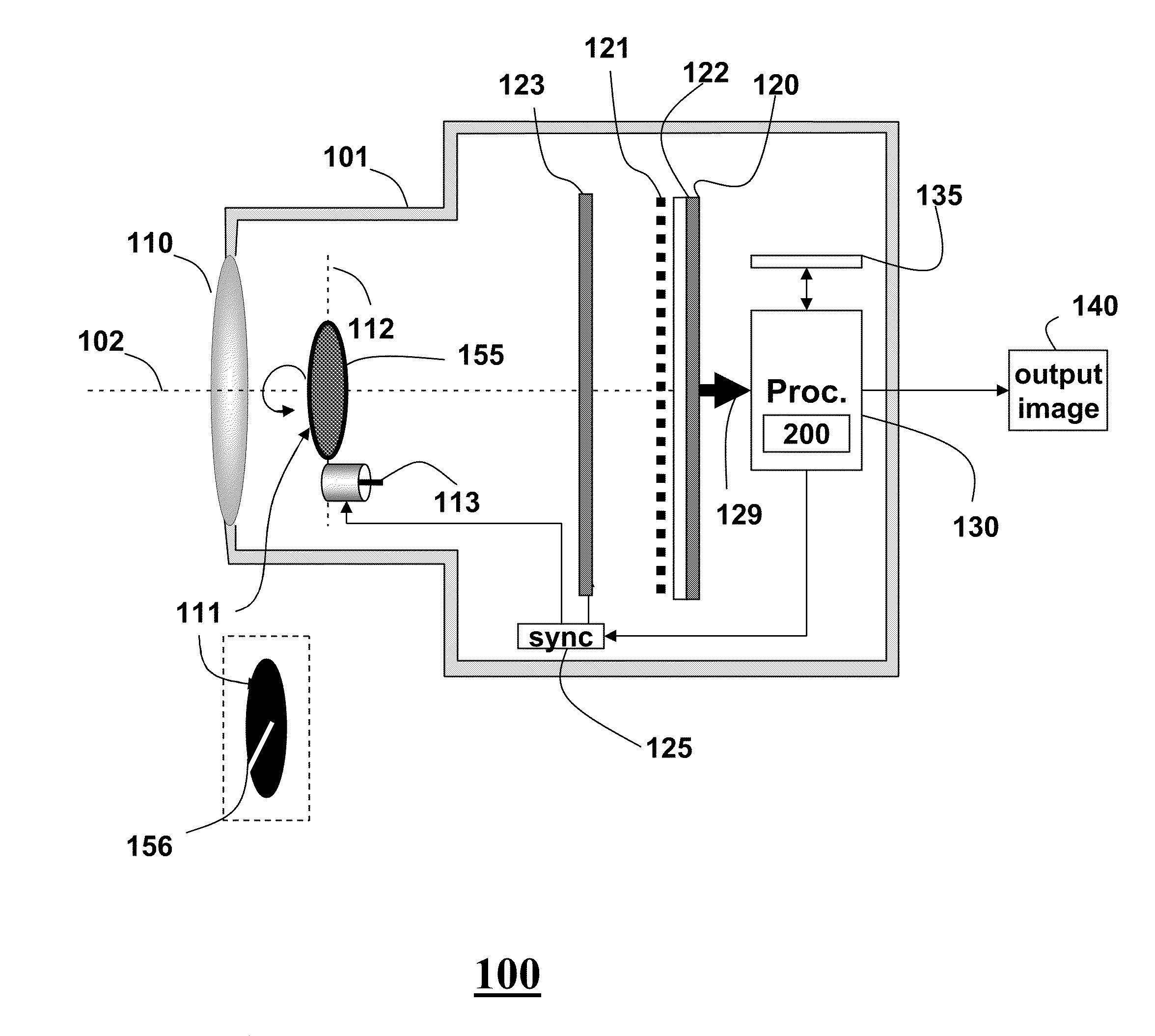
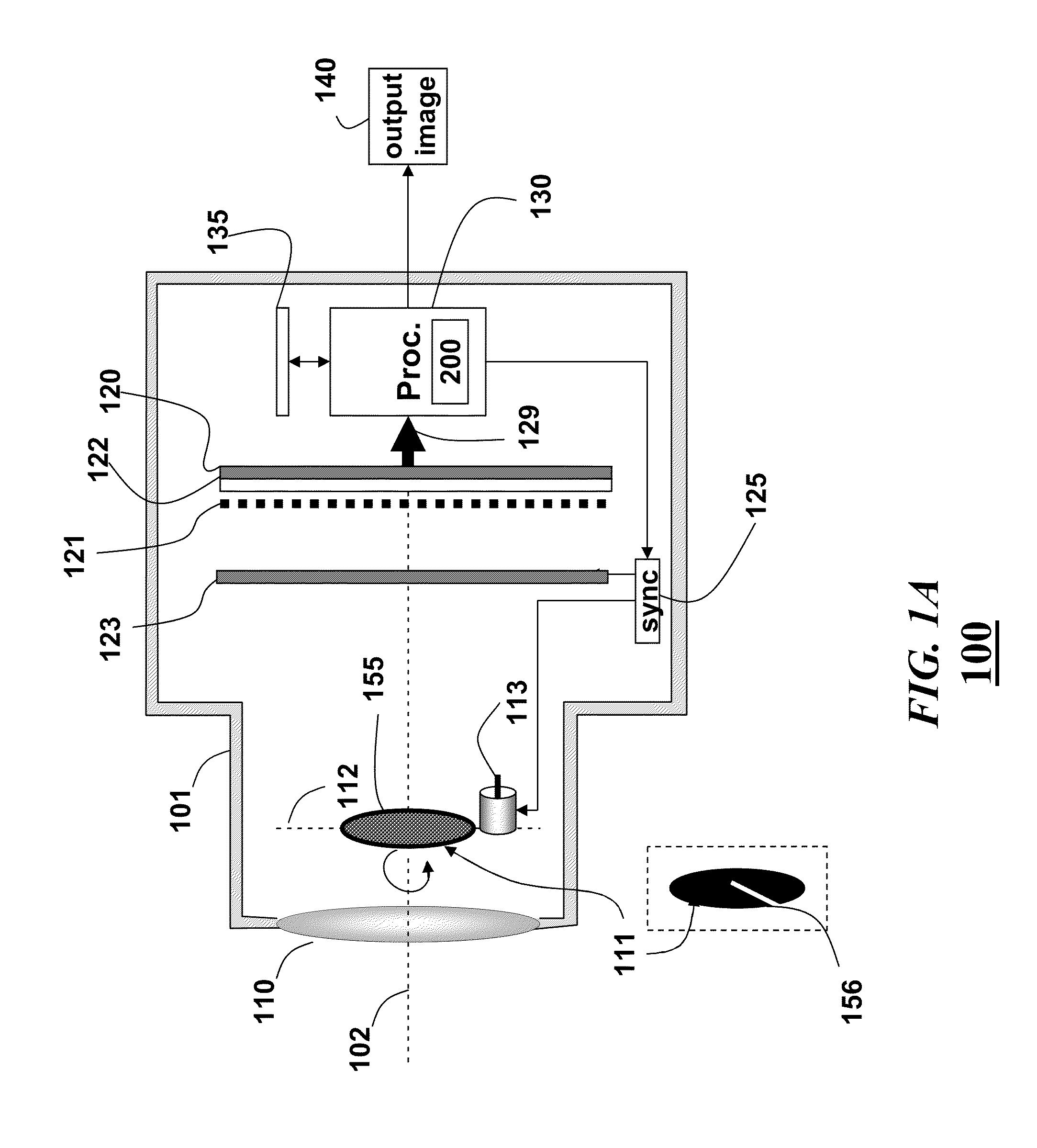
[0028]FIG. 1A shows an apparatus 100 and method 200 according to embodiments of our invention. The Figure is not to scale, and elements are placed to easier show various features. The apparatus is in the form of camera arranged inside a body 101. The camera includes a lens 110 and a sensor 120. A dynamic mask 111 is placed at an aperture plane 112. A static heterodyne mask 121 is placed immediately adjacent to the sensor. That is, the mask 121 is placed on or near the surface of the sensor facing the lens. The optical elements are aligned on an optical axis 102 of the camera.

[0029]The camera also includes a processor 130 for performing steps of the method 200. The processor can be a single or multi-core microprocessor as known in then art, including input / output interfaces and memories. The processor can perform conventional functions, such as image stabilization, zoom, exposure and focus control, noise reduction, image organization, and the like. The method 200 is performed on a si...


PUM


Abstract

A camera includes a lens and a sensor. A dynamic mask is arranged at an aperture plane between the lens and the sensor, and a static mask is arranged immediately adjacent to the sensor. Angular, temporal or spatial variations in light rays acquired of a scene by the sensor are mapped to individual pixels of the sensor.

Description

FIELD OF THE INVENTION[0001]This invention relates generally to cameras and computational photography, and more particularly to trading-off spatio-angular-temporal resolutions in images acquired with cameras equipped with masks in the optical path.BACKGROUND OF THE INVENTIONComputational Photography[0002]One goal of computational photography is to trade-off simplicity of image acquisition and enhanced post-processing. For example, a lower spatial resolution can be traded-off for a higher angular resolution to support digital refocusing. Similarly, high speed cameras trade-off spatial resolution for temporal resolution.[0003]A focused micro-lens (lenslet) array placed near or on a camera sensor can sample angular variations at the aperture plane of the camera at spatial location of the sensor to acquire a low spatial resolution light field. Alternatively, a combination of a positive lens and prism can placed in front of the main lens. Frequency domain modulation of light fields is al...

Claims


Application Information

Patent Timeline
IPC IPC(8): G03B41/00
CPCH04N5/23229H04N5/2254G02B27/1066H04N23/80
Inventor AGRAWAL, AMIT KUMARVEERARAGHAVAN, ASHOK
Owner MITSUBISHI ELECTRIC RES LAB INC
Why Eureka
Try Eureka