Imaging tomography apparatus with at least two radiator-detector combinations

a tomography apparatus and radiator technology, applied in tomography, instruments, nuclear engineering, etc., can solve the problems of increasing increasing the acceleration force, and mechanical problems, so as to reduce the fan angle of the acquisition system with the large measurement field, the effect of reducing the radiation and reducing the frequency of the chang

Active Publication Date: 2005-04-28
SIEMENS HEALTHCARE GMBH
View PDF19 Cites 57 Cited by
  • Summary
  • Abstract
  • Description
  • Claims
  • Application Information

AI Technical Summary

Benefits of technology

[0012] The problem of the measurement field being too severely restricted can be solved by a combination of a radiator-detector combinations that covers the entire measurement field with one or more radiator-detector combinations that each cover only a limited measurement field. For example, an image is thereby obtained of the whole body cross-section with normal temporal resolution, and a representation of the heart region is obtained with increased temporal resolution. The number of the possible acquisition systems or radiator-detector combinations depends on the special device geometry and the desired actual measurement field. The tomography device is also advantageous for examination of inanimate items, for example luggage, because it allows both a larger region and a smaller region to be scanned with high quality.
[0021] Among other things, in this embodiment the detectors are particularly advantageously mounted on the respective acquisition system, such that after a common rotation of both acquisition systems (which transfers an imaginary connecting line “first focus of the first radiator—rotation center” to the previous position of an imaginary connecting line “second focus of the second radiator —rotation center”), at least some of the detector elements of the first detector come to lie at a displacement angle, for example equal to the half element separation, displaced with regard to the previous positions of the detector elements of the second detector. This has the advantage that a finer scanning of the examination subject or patient ensues that corresponds in effect to what is known as a springing focus. Scanning errors are thereby minimized. This preferred embodiment is also of advantage in a tomography device with two or more acquisition systems with an identical fan angle or measurement field.
[0025] Preferably, in the tomography device according to the invention, both acquisition systems are arranged in a common plane. From this in particular, the advantage arises of an increased temporal resolution in the representation of movement cycles in comparison to known systems.
[0027] For minimization of the radiation dosage, preferably an arrangement to minimize the radiation, associated with the acquisition system with the larger maximum measurement data, is present in the region of the larger measurement field, and in which region the larger measurement field does not overlap with the smaller measurement field of the other acquisition system. For example, an unnecessary radiation exposure in the region outside of the human heart can thereby be reduced or prevented, in the event that only the head should be scanned.
[0028] Such an arrangement can be, for example, a gating device with which the fan angle of the acquisition system with the large measurement field can be decreased, in particular can be continuously decreased.

Problems solved by technology

Conventionally, this has been attempted to be achieved by increasing the rotation speed of the acquisition system, but the acceleration forces, and the mechanical problems resulting therefrom, increase significantly with additional rotation speed.

Method used


Image

  • Imaging tomography apparatus with at least two radiator-detector combinations
  • Imaging tomography apparatus with at least two radiator-detector combinations
  • Imaging tomography apparatus with at least two radiator-detector combinations

Examples


Embodiment Construction

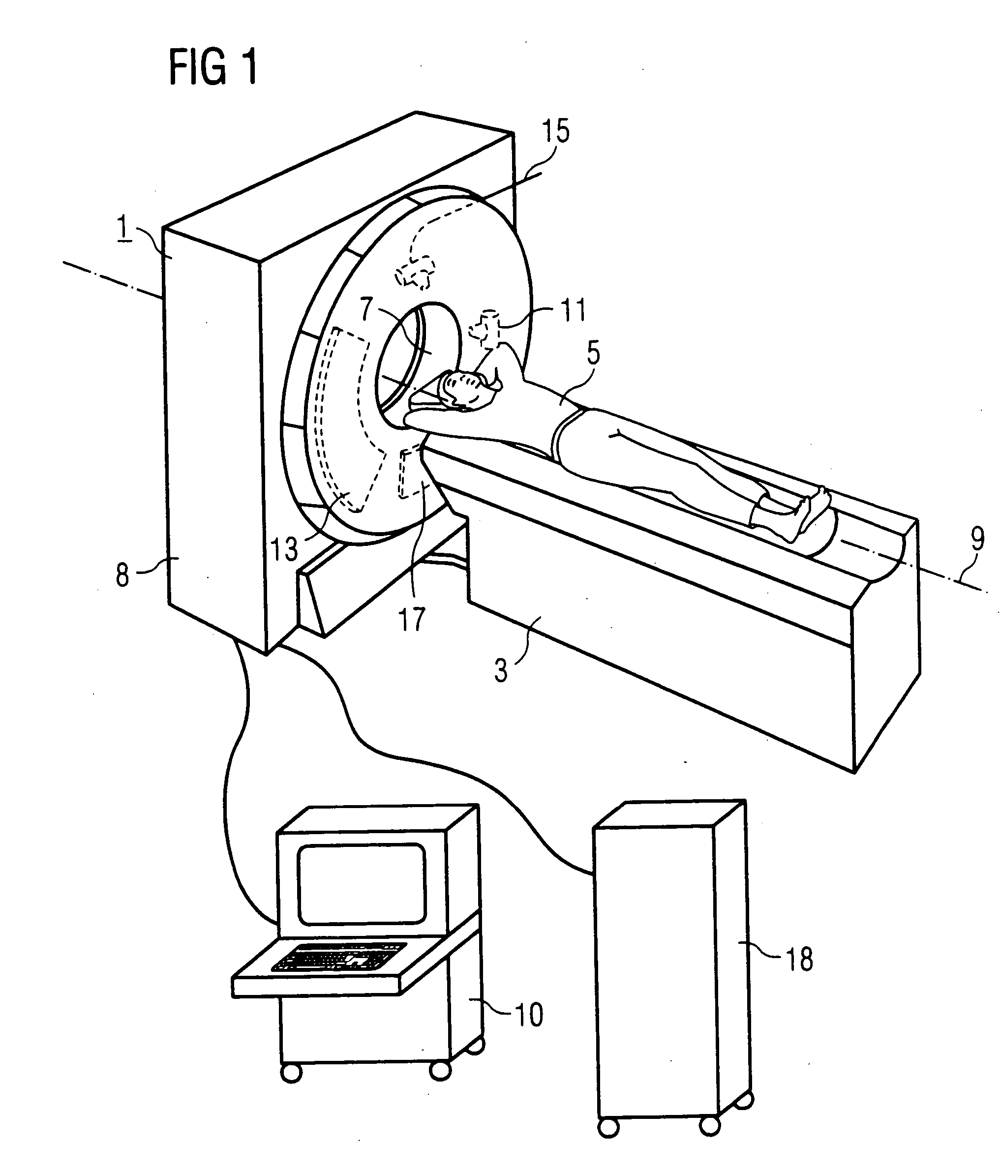
[0039] Two exemplary embodiments of a tomography apparatus according to the invention are subsequently explained in detail using FIGS. 1 through 4.

[0040]FIG. 1 shows a tomography apparatus 1 (here an x-ray computed tomography apparatus) with an associated positioning device 3 for exposure and positioning of a patient 5. The patient 5 with the desired examination region or scan region can be inserted into an opening 7 (diameter 70 cm) in the housing 8 of the tomography device 1 by means of a movable table top of the positioning device 3. Moreover, in the case of a spiral scan, a continuous axial feed is effected with the positioning device 3.

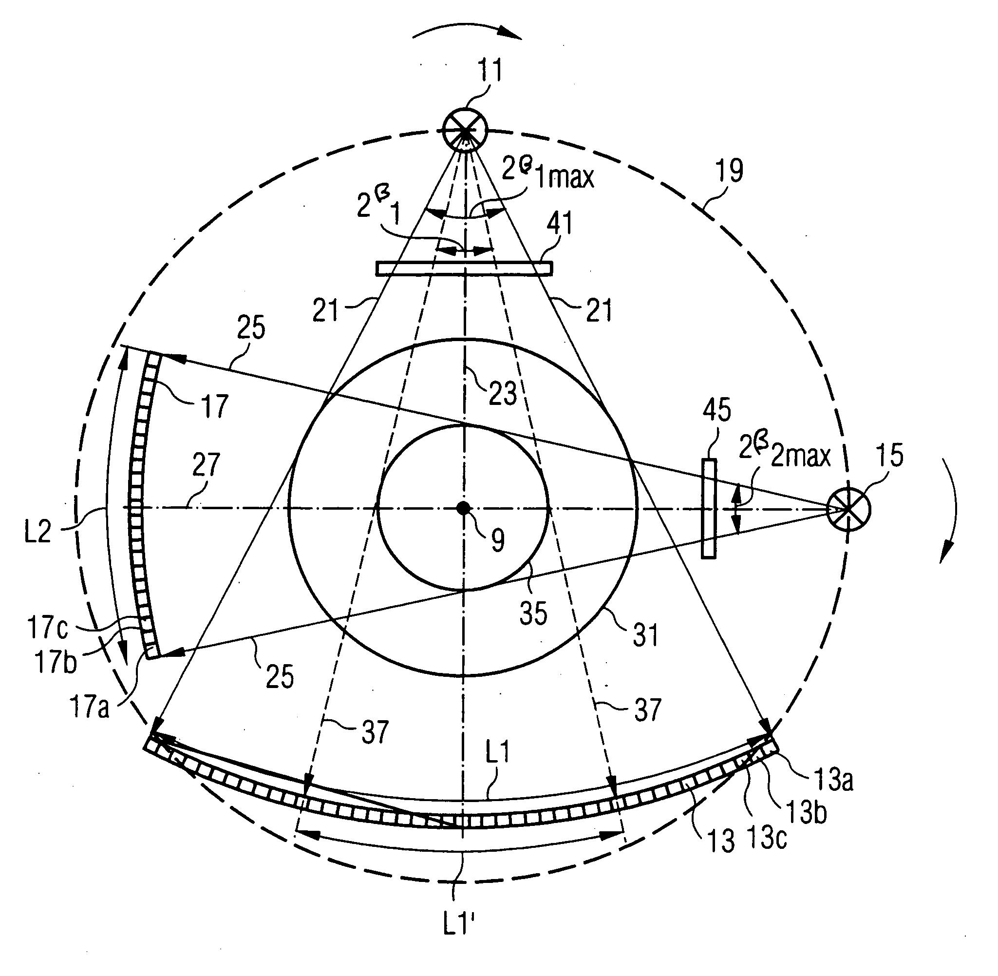
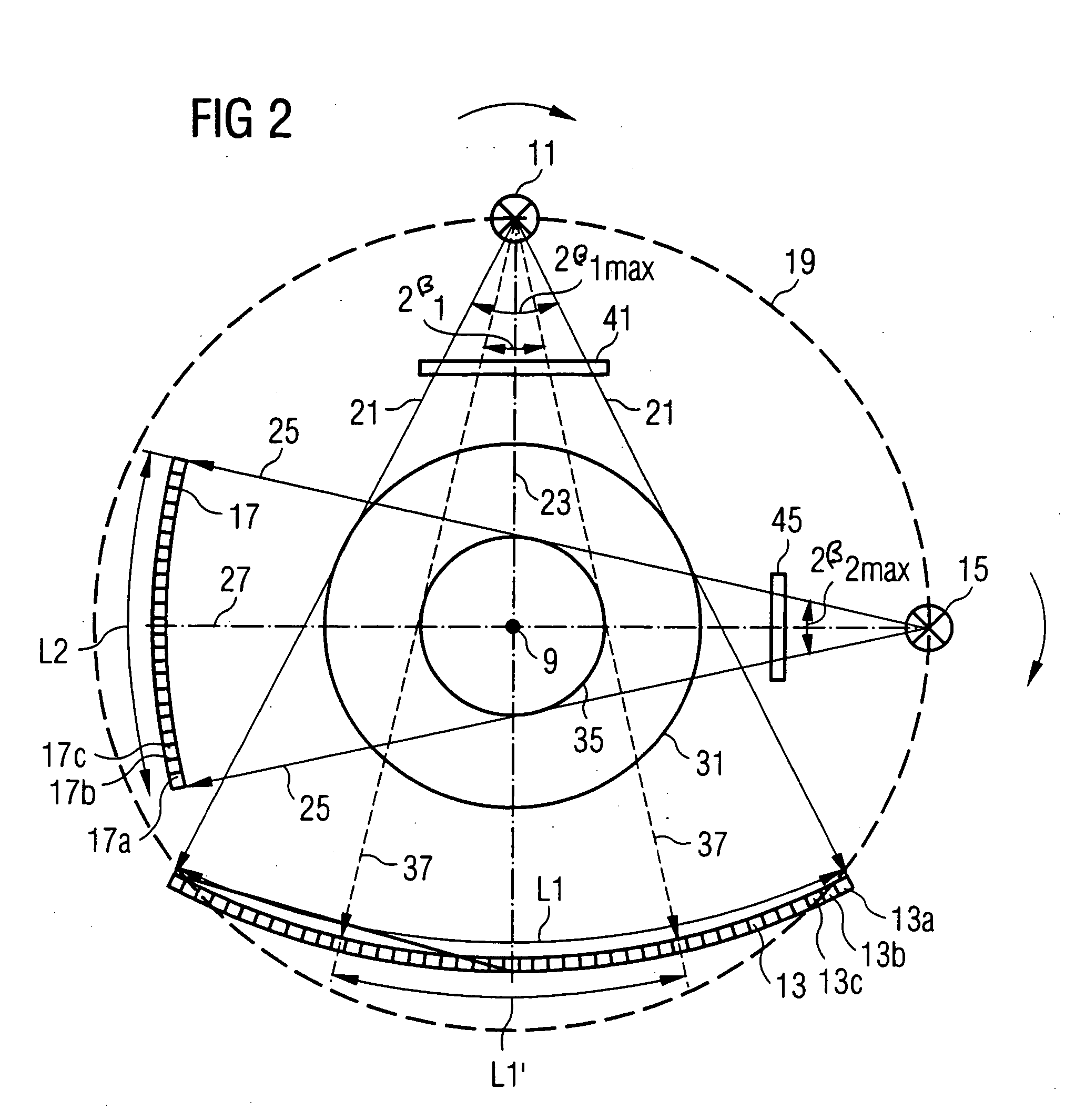
[0041] Inside the housing 8, a gantry (not visible in FIG. 1) can be rotated with high speed around a rotation axis 9 running through the patient 5.

[0042] An operating unit 10 is present for operation of the tomography device 1 by a doctor or the like.

[0043] To achieve a short scan time and / or a high temporal resolution, a number of acquisiti...


PUM

PropertyMeasurementUnit
fan angleaaaaaaaaaa
fan angle 2β2maxaaaaaaaaaa
diameteraaaaaaaaaa

Abstract

An imaging tomography apparatus, in particular an x-ray computed tomography apparatus, has two acquisition systems capable of rotating around a common rotation axis. Each of the acquisition systems has a radiator as well as a detector. The maximum measurement fields scanned by the two acquisition systems given rotation around the rotation axis are of different sizes, or can be adjusted to different sizes. In particular, the lengths of both detectors measured in the azimuthal direction—are of different sizes. The tomography apparatus can be fashioned to scan the entire body cross-section of an examination subject or of a patient with conventional temporal resolution, and to scan detail region, such as a heart region, with an increased temporal resolution or accelerated data acquisition rate in comparison to a device with only one acquisition system.

Description

BACKGROUND OF THE INVENTION [0001] 1. Field of the Invention [0002] The present invention concerns an imaging tomography apparatus, in particular an x-ray computed tomography apparatus, of the type having at least a first acquisition system (with a first radiator and a first detector for detection of the radiation originating from the first radiator) and a second acquisition system (comprising a second radiator and a second detector for detection of the radiation originating from the second radiator), wherein both acquisition systems are capable of rotating around a common rotation axis. [0003] 2. Description of the Prior Art [0004] Tomography apparatuses of the above type are known from U.S. Pat. Nos. 4,991,190; 4,384,359; 4,196,352; 5,966,422 and 6,421,412. An advantage that such tomography apparatuses with multiple acquisition systems exhibit in comparison to a device with one acquisition system is an increased data acquisition rate, which leads to a shorter exposure time, and / or...

Claims


Application Information

Patent Timeline
Patent Type & Authority Applications(United States)
IPC IPC(8): A61B6/03G01N23/04
CPCA61B6/032A61B6/4085G01N2223/612A61B6/4021G01N2223/419G01N23/046
Inventor BRUDER, HERBERTFLOHR, THOMASPAULI, KARLHEINZSIMON, JUERGEN
Owner SIEMENS HEALTHCARE GMBH
Why Eureka
Try Eureka