
Method and apparatus for encoding and decoding an audio signal using adaptively switched temporal resolution in the spectral domain

a technology of adaptive switching and temporal resolution, applied in the field of methods and apparatus for encoding and decoding an audio signal, can solve the problems of preventing providing a sufficient resolution for optimal irrelevancy reduction, and achieve the effects of improving coding/decoding gain, high frequency resolution, and high temporal resolution

Active Publication Date: 2009-01-08
GUANGDONG OPPO MOBILE TELECOMM CORP LTD
View PDF16 Cites 57 Cited by
  • Summary
  • Abstract
  • Description
  • Claims
  • Application Information

AI Technical Summary

Benefits of technology

The invention provides an improved coding / decoding method and apparatus for audio signals that uses high frequency resolution and temporal resolution for transient audio signal parts. The method and apparatus apply a cascaded MDCT and quantization and entropy encoding techniques to achieve better resolution and reduced delay. The invention achieves improved coding / decoding quality by applying switching to an additional extension filter bank and controlling the temporal resolution. The invention also includes a method for providing a high-resolution output signal by performing a second forward transform and inversely quantizing and entropy decoding the output. The technical effects of the invention include improved coding / decoding quality, reduced delay, and improved temporal resolution for transient audio signal parts.

Problems solved by technology

The above-mentioned window and / or transform length switching disclosed by Edler is sub-optimum because of long delay due to long look-ahead and low frequency resolution of short blocks, which prevents providing a sufficient resolution for optimum irrelevancy reduction.

Method used


Image

  • Method and apparatus for encoding and decoding an audio signal using adaptively switched temporal resolution in the spectral domain
  • Method and apparatus for encoding and decoding an audio signal using adaptively switched temporal resolution in the spectral domain
  • Method and apparatus for encoding and decoding an audio signal using adaptively switched temporal resolution in the spectral domain

Examples


Embodiment Construction

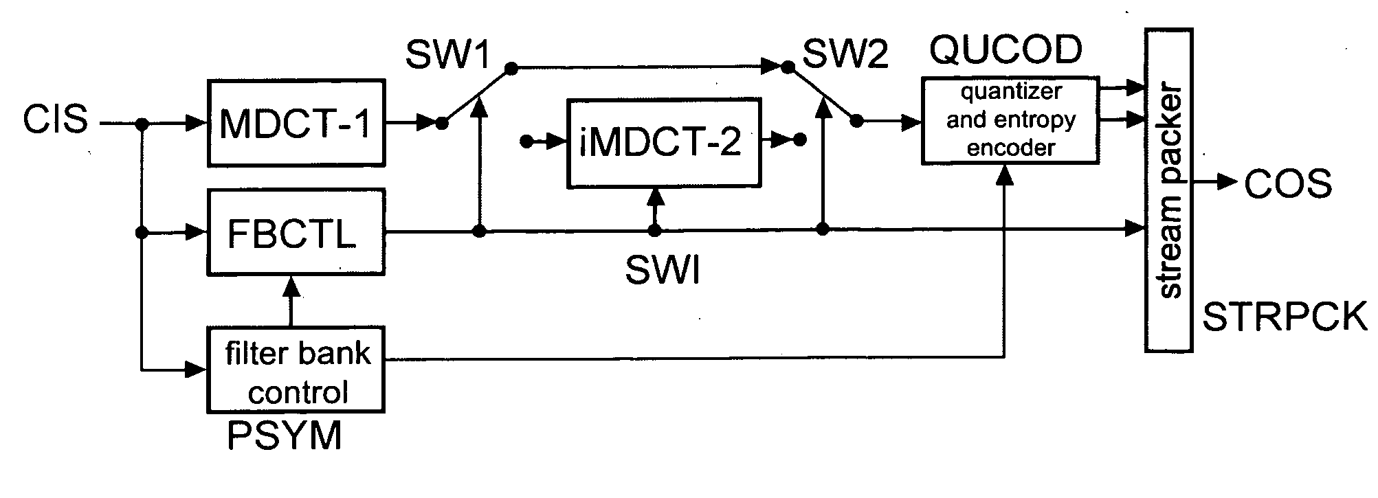
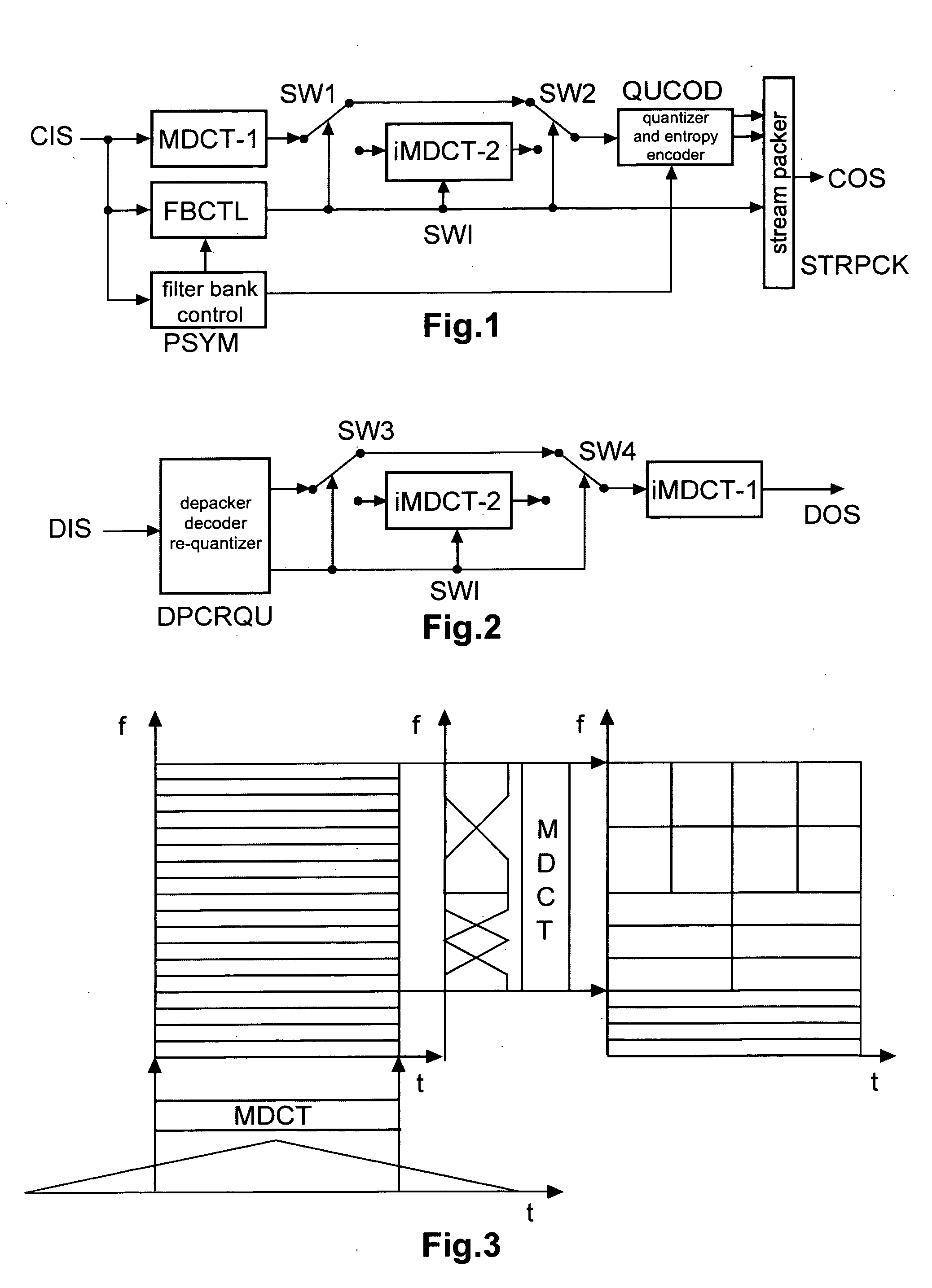
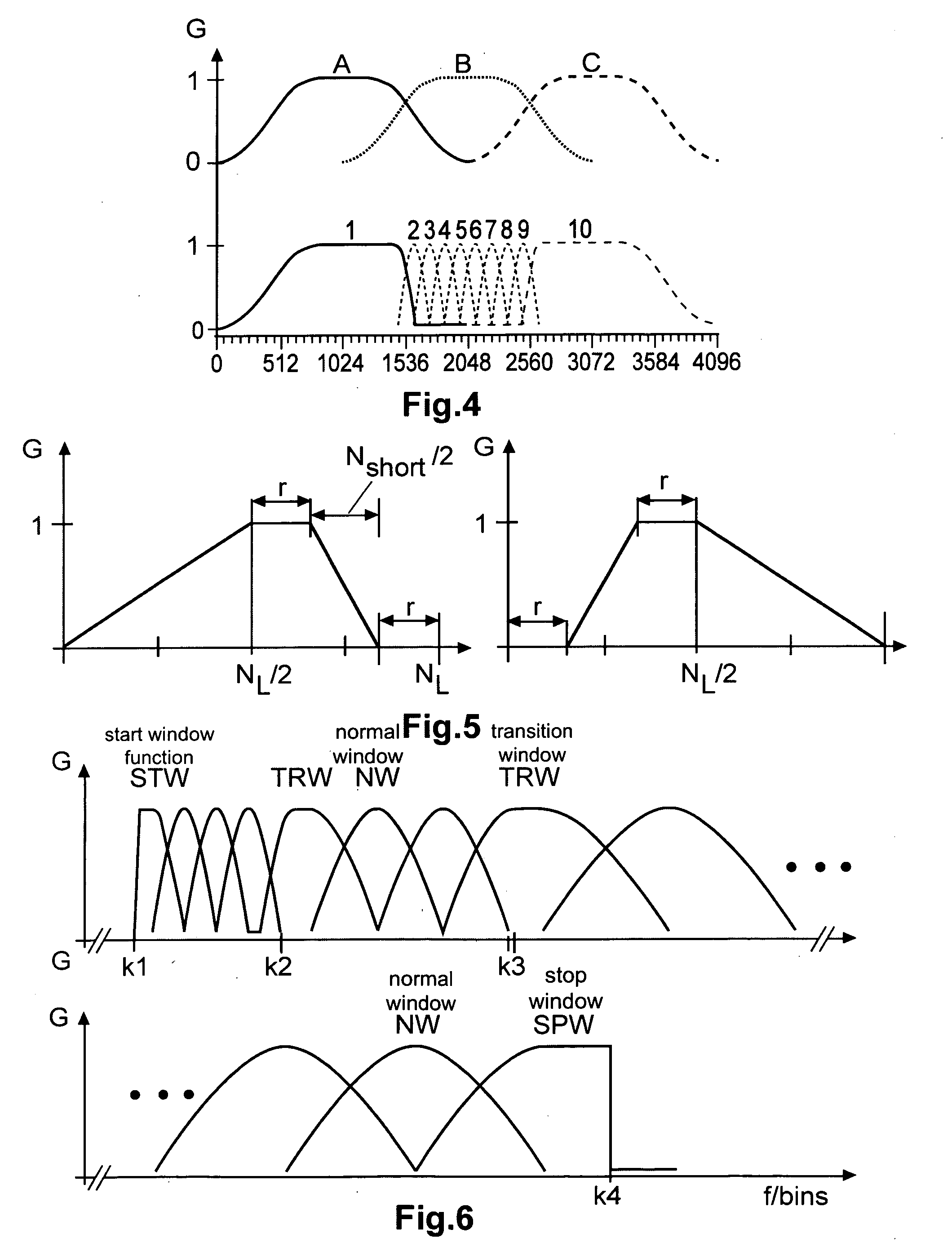
[0037]In FIG. 1, the magnitude values of each successive overlapping block or segment or section of samples of a coder input audio signal CIS are weighted by a window function and transformed in a long (i.e. a high frequency resolution) MDCT filter bank or transform stage or step MDCT-1, providing corresponding transform coefficients or frequency bins. During transient audio signal sections a second MDCT filter bank or transform stage or step MDCT-2, either with shorter fixed transform length or preferably a multi-resolution MDCT filter bank having different shorter transform lengths, is applied to the frequency bins of the first forward transform (i.e. on the same block) in order to change the frequency and temporal filter resolutions, i.e. a series of non-uniform MDCTs is applied to the frequency data, whereby a non-uniform time / frequency representation is generated. The amplitude values of each successive overlapping section of frequency bins of the first forward transform are we...


PUM


Abstract

Perceptual audio codecs make use of filter banks and MDCT in order to achieve a compact representation of the audio signal, by removing redundancy and irrelevancy from the original audio signal. During quasi-stationary parts of the audio signal a high frequency resolution of the filter bank is advantageous in order to achieve a high coding gain, but this high frequency resolution is coupled to a coarse temporal resolution that becomes a problem during transient signal parts by producing audible pre-echo effects. The invention achieves improved coding / decoding quality by applying on top of the output of a first filter bank a second non-uniform filter bank, i.e. a cascaded MDCT. The inventive codec uses switching to an additional extension filter bank (or multi-resolution filter bank) in order to re-group the time-frequency representation during transient or fast changing audio signal sections. By applying a corresponding switching control, pre-echo effects are avoided and a high coding gain and a low coding delay are achieved.

Description

FIELD OF THE INVENTION[0001]The invention relates to a method and to an apparatus for encoding and decoding an audio signal using transform coding and adaptive switching of the temporal resolution in the spectral domain.BACKGROUND OF THE INVENTION[0002]Perceptual audio codecs make use of filter banks and MDCT (modified discrete cosine transform, a forward transform) in order to achieve a compact representation of the audio signal, i.e. a redundancy reduction, and to be able to reduce irrelevancy from the original audio signal. During quasi-stationary parts of the audio signal a high frequency or spectral resolution of the filter bank is advantageous in order to achieve a high coding gain, but this high frequency resolution is coupled to a coarse temporal resolution that becomes a problem during transient signal parts. A well-know consequence are audible pre-echo effects.[0003]B. Edler, “Codierung von Audiosignalen mit ütberlappender Transformation und adaptiven Fensterfunktionen”, F...

Claims


Application Information

Patent Timeline
Patent Type & Authority Applications(United States)
IPC IPC(8): G10L19/00G10L19/02G10L19/022
CPCG10L19/022G10L19/0212G10L19/02G10L19/03
Inventor BOEHM, JOHANNESKORDON, SVEN
Owner GUANGDONG OPPO MOBILE TELECOMM CORP LTD
Learn More