Electromagnetic spectral-based imaging devices and methods

a technology of electromagnetic spectral and imaging device, applied in the field of electromagnetic spectral-based imaging device and method, can solve the problems of inability to resolve small increments of spectrum in the visible light wave region, flawed reliance on metameric rgb color space model to create a full palette of colors, etc., and achieve the effect of low noise and tremendous sensitivity

Active Publication Date: 2009-04-21
ROSENTHAL ERIC DEAN +2
View PDF8 Cites 1 Cited by
  • Summary
  • Abstract
  • Description
  • Claims
  • Application Information

AI Technical Summary

Benefits of technology

[0008]Embodiments of this present invention take advantage of the wave properties of light, and therefore use tiny components dimensioned to the wavelengths of light. Recent developments in nano-technology permit construction of wave-sensitive receivers, instead of photon-sensitive devices. These receivers can operate in the light range, with consequent low noise and tremendous sensitivity due to gain resulting from their inherent antenna construction.

Problems solved by technology

In other words, our reliance on metameric RGB color space models to create a full palate of colors is flawed.
Such methods are too crude to resolve small increments of spectrum in the visible light wave region.

Method used


Image

  • Electromagnetic spectral-based imaging devices and methods
  • Electromagnetic spectral-based imaging devices and methods
  • Electromagnetic spectral-based imaging devices and methods

Examples


Embodiment Construction

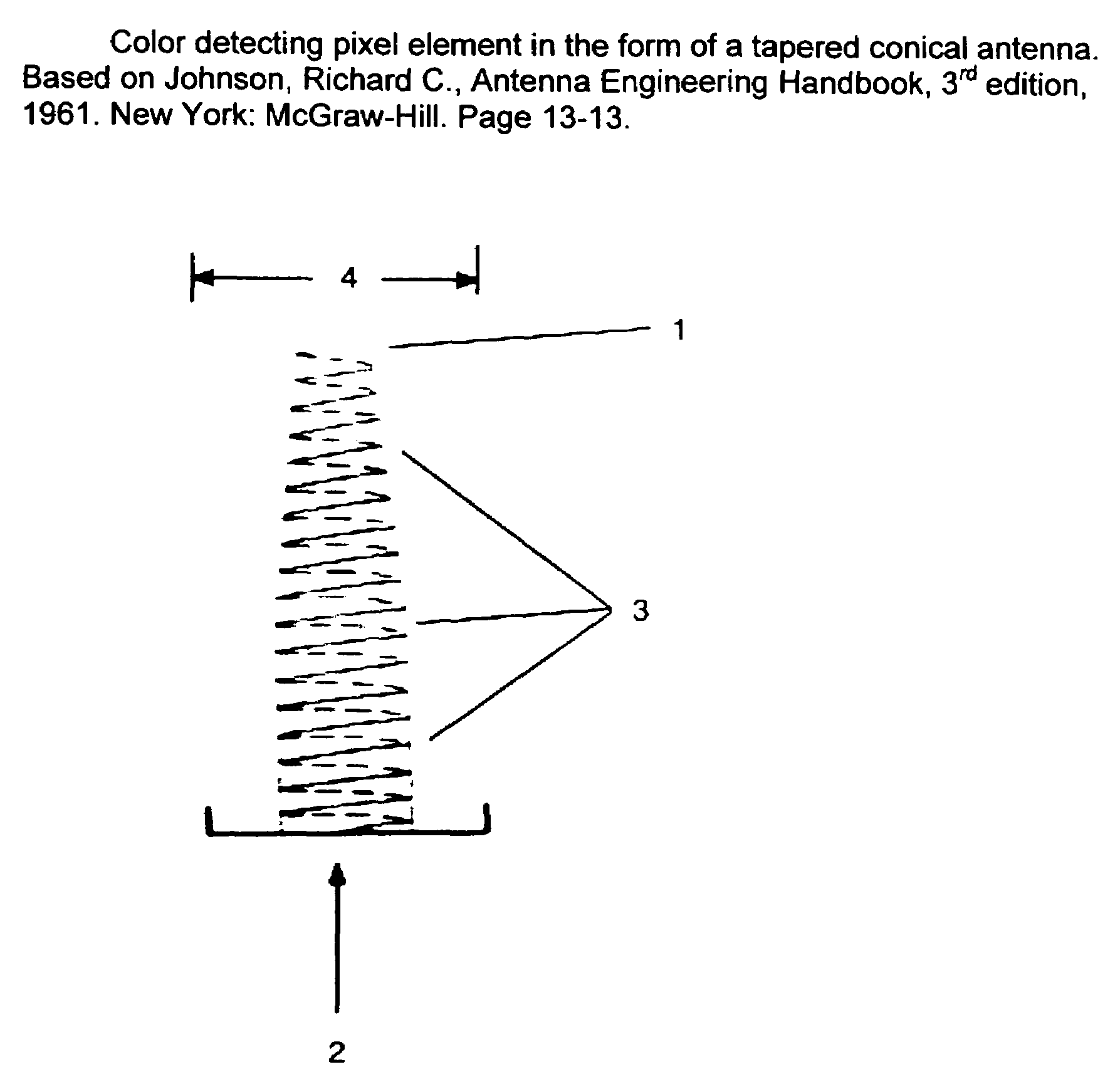
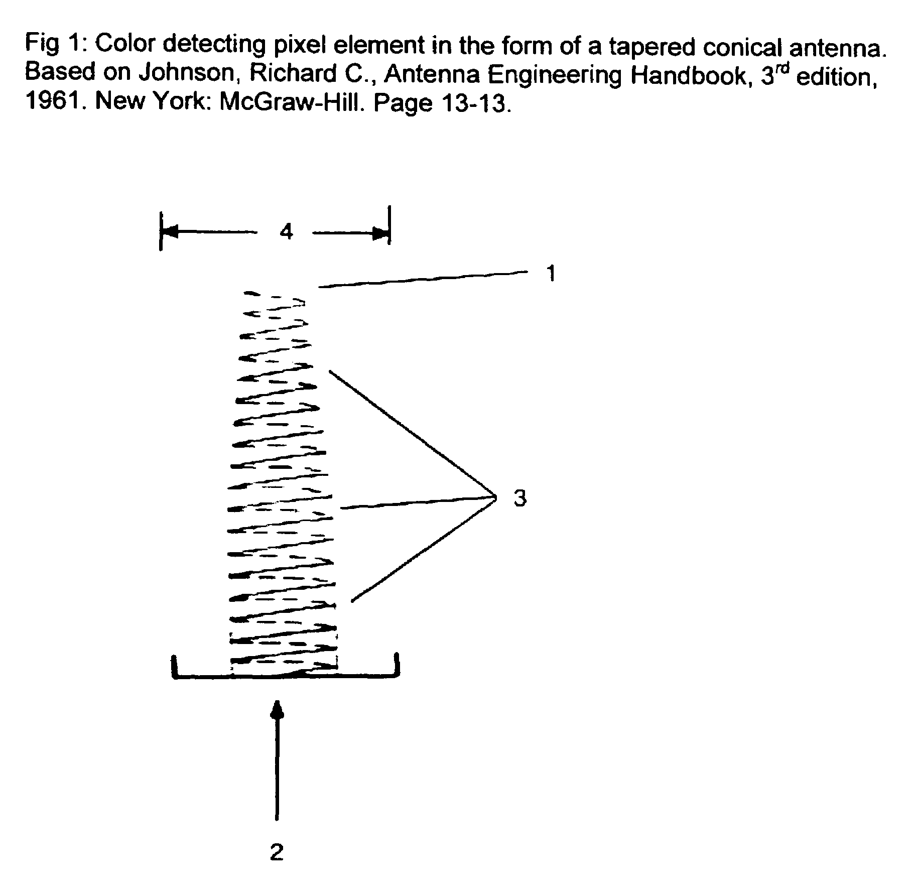
[0031]Definitions. As used in this description the following terms shall have the meanings indicated unless the context otherwise requires:

[0032]“Array” means a structured arrangement of elements. An “antenna array” in accordance with the present invention, however, does not necessarily have to provide outputs that are scanned linearly as in a CCD array for example. Rather, the elements may be sampled in a wide range of ways depending upon the desired operating environment.

[0033]“Spectral composition” means the spectral signature of a detected complex waveform.

[0034]“Decomposition” means the function of segmenting the signature into narrow bands for ultimate analysis. Colors as seen by humans are an example of spectral decomposition of visible light.

[0035]“Dithering” the sweeping of the frequency of a reference signal means substantially slowing the rate of sweeping of the reference signal. As described in connection with heterodyning below, this slowing is typically implemented to ...


PUM


Abstract

This invention teaches how to fabricate a new type of full-spectra wavelength detector and spectrum analyzer in the form of antennas that make use of the wave properties of light. The detector's frequency detection range is controlled through the fabrication process. By miniaturizing the antenna detectors to the nanometer range and arranging them in an array a unique, full-spectrum imaging sensor is created.

Description

[0001]The present application claims priority from our provisional applications Ser. No. 60 / 527,328 filed on 5 Dec. 2003 and Ser. No. 60 / 529,691 dated 13 Dec. 2003 and filed on 15 Dec. 2003; these applications are hereby incorporated herein by reference.TECHNICAL FIELD AND BACKGROUND ART[0002]The present invention relates to imaging devices and methods, pertinent to electromagnetic energy in visual and other spectra, aimed at capturing and reproducing substantially all image information in a relevant spectrum.[0003]In order to achieve truly full-spectrum images, it has long been deemed necessary to detect the full color gamut of the image, and not just the conventional three Red-Green-Blue (RGB) band-pass filtered colors. Most cameras detect color by separating the image into these three components, passing each component through an absorption filter and thence onto three detectors. Two-thirds of the light energy is lost in this process.[0004]Recent studies have shown that while any...

Claims


Application Information

Patent Timeline
Patent Type & Authority Patents(United States)
IPC IPC(8): G01J1/04
CPCG01J3/02G01J3/0291G01J3/10G01J3/18G01J3/2823H01Q11/083Y10S977/902Y10S977/70
Inventor ROSENTHAL, ERIC DEANSOLOMON, RICHARD JAYJOHNSON, CLARK EUGENE
Owner ROSENTHAL ERIC DEAN
Why Eureka
Try Eureka