Liquid crystal display device

A liquid crystal display device, liquid crystal composition technology, applied in the direction of liquid crystal materials, instruments, chemical instruments and methods, etc., can solve problems such as uneven orientation, white spots, and reduction, and achieve the effect of preventing reduction and preventing white spots

Active Publication Date: 2014-11-05
DIC CORP
View PDF6 Cites 1 Cited by
  • Summary
  • Abstract
  • Description
  • Claims
  • Application Information

AI Technical Summary

Problems solved by technology

[0016] The present invention provides a liquid crystal display device that prevents the reduction of the voltage holding ratio (VHR) of the liquid crystal layer, ion density, and The increase of (ID) solves the problems of poor display such as white spots, uneven orientation, and screen burn-in

Method used


Image

  • Liquid crystal display device
  • Liquid crystal display device
  • Liquid crystal display device

Examples


Embodiment 1~4

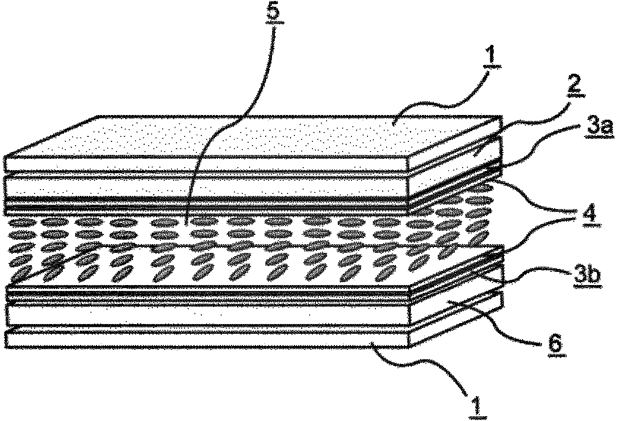
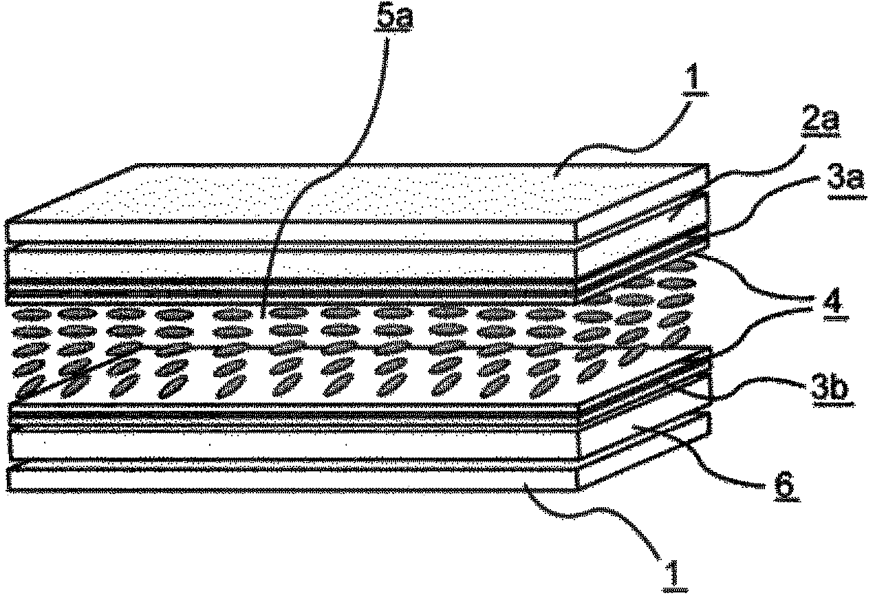
[0291] Make an electrode structure on at least one of the first and second substrates, form a horizontally oriented orientation film on the respective opposite sides, and then perform a weak rubbing treatment to make an IPS unit, sandwich the first substrate and the second substrate Liquid crystal composition 1 shown below was used. Table 4 shows the physical property values ​​of the liquid crystal composition 1. Then, using the color filters 1 to 4 shown in Table 2, the liquid crystal display devices (d gap =4.0 μm, alignment film AL-1051). The VHR and ID of the obtained liquid crystal display device were measured. In addition, burn-in evaluation of the obtained liquid crystal display device was performed. The results are shown in Table 5.
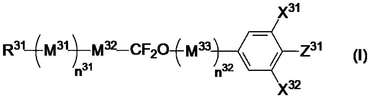
[0292] [chem 22]

[0293]

[0294] [Table 4]

[0295] T NI / ℃

75.8

Δn

0.112

no

1.488

ε ⊥

5.5

Δε

2.9

η / mPa·s

13.5

[0296] [table 5]

[0297] ...

Embodiment 5~12

[0301] Liquid crystal display devices of Examples 5 to 12 were prepared using the color filters shown in Table 2 by sandwiching liquid crystal compositions 2 to 3 shown in Table 5 in the same manner as in Example 1, and their VHR and ID were measured. Moreover, the burn-in evaluation of this liquid crystal display device was performed. The results are shown in Tables 7-8.

[0302] [Table 6]

[0303]

[0304] [Table 7]

[0305]

[0306] [Table 8]

[0307]

[0308] The liquid crystal display devices of Examples 5 to 12 realized high VHR and small ID. In addition, in the evaluation of burn-in, there was no afterimage, or even if there was an afterimage, it was very small, which was at an allowable level.

Embodiment 13~24

[0310]Liquid crystal display devices of Examples 13 to 24 were prepared using the color filters shown in Table 2 by sandwiching liquid crystal compositions 4 to 6 shown in Table 9 in the same manner as in Example 1, and their VHR and ID were measured. Moreover, the burn-in evaluation of this liquid crystal display device was performed. The results are shown in Tables 10-12.

[0311] [Table 9]

[0312]

[0313] [Table 10]

[0314]

[0315] [Table 11]

[0316]

[0317] [Table 12]

[0318]

[0319] The liquid crystal display devices of Examples 13 to 24 realized high VHR and small ID. In addition, in the evaluation of burn-in, there was no afterimage, or even if there was an afterimage, it was very small, which was at an allowable level.


PUM

PropertyMeasurementUnit
coating thicknessaaaaaaaaaa

Abstract

The present invention relates to a liquid crystal display device including a particular liquid crystal composition and a color filter that uses a particular pigment. The present invention provides a liquid crystal display device in which a decrease in the voltage holding ratio (VHR) of a liquid crystal layer and an increase in the ion density (ID) are prevented and problems of display defects such as white streaks, alignment unevenness, and image sticking are overcome. The liquid crystal display device of the present invention in which a decrease in the voltage holding ratio (VHR) of a liquid crystal layer and an increase in the ion density (ID) are prevented and problems of display defects such as image sticking are overcome is particularly useful for active matrix driving liquid crystal display devices with an IPS mode and an FFS mode and can be applied to liquid crystal display devices of liquid crystal televisions, monitors, cellular phones, and smart phones.

Description

technical field [0001] The present invention relates to a liquid crystal display device. Background technique [0002] From clocks and calculators, liquid crystal display devices have gradually been used in various household electrical equipment, measurement equipment, automotive panels, word processors, electronic notebooks, printers, computers, televisions, etc. Representative examples of liquid crystal display methods include TN (twisted nematic) type, STN (super twisted nematic) type, DS (dynamic light scattering) type, GH (guest-host) type, IPS (in-plane switching) type, and OCB type. (Optically Compensated Birefringence) type, ECB (Voltage Controlled Birefringence) type, VA (Vertical Alignment) type, CSH (Color Super Vertical) type, or FLC (Ferroelectric Liquid Crystal) and the like. In addition, as the driving method, from the conventional static driving, multiplex driving has become common, and the simple matrix method, and recently the active matrix (AM) method dri...

Claims


Application Information

Patent Timeline
Patent Type & Authority Applications(China)
IPC IPC(8): G02F1/1335C09K19/12C09K19/20C09K19/30C09K19/34C09K19/38C09K19/54G02B5/20G02F1/13
CPCG02B5/20C09K19/12C09K19/20C09K19/54C09K19/38C09K19/34G02F2001/133397C09K19/30G02F1/133514G02F2202/04C09K19/3066C09K19/44C09K2019/0448C09K2019/0466C09K2019/122C09K2019/123C09K2019/3004C09K2019/301C09K2019/3016C09K2019/3422G02F1/133397C09K19/08C09K19/42G02F1/13G02F1/133512
Inventor 栗山毅河村丞冶木村亮船仓省二岛田胜德
Owner DIC CORP
Why Eureka
Try Eureka