Harvester Fuhe Mechanism

A harvester and Fuhe finger technology, applied in the field of harvesters, can solve problems such as unsuitable operating speed and working state, unfavorable operating speed and working efficiency, and difficult manufacturing, so as to improve the working range and quality, reduce energy consumption, The effect of simple manufacturing process

Inactive Publication Date: 2016-06-22
何嘉俊
View PDF8 Cites 0 Cited by
  • Summary
  • Abstract
  • Description
  • Claims
  • Application Information

AI Technical Summary

Problems solved by technology

[0002] In the original semi-feeding harvester's grain-supporting board, the chain drives the grain-supporting finger to run from top to bottom. At the upper end, there is a mechanism for folding the grain-supporting finger into the grain-supporting board. The plate lifts the grain from bottom to top, and there are many components, which is not conducive to improving the running speed and work efficiency. The original chain drives the grain-feeding finger of the grain-feeding guide to the tail below the block in the grain-feeding mechanism of the upper-mounted semi-feeding combine harvester. A section of arc track protrudes during bending operation, and the upper cover plate of the Fuhe must be constructed to accommodate this protruding arc track, which is difficult to manufacture, and is not suitable for the non-folding and extending of the Fuhe finger, and it is also not suitable for the running speed. Improved working condition

Method used


Image

  • Harvester Fuhe Mechanism
  • Harvester Fuhe Mechanism
  • Harvester Fuhe Mechanism

Examples


Embodiment Construction

[0028] The present invention will be described in further detail below in conjunction with the accompanying drawings and specific embodiments.

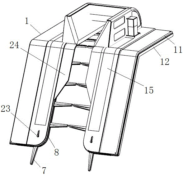
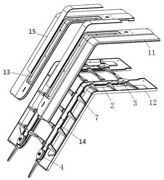
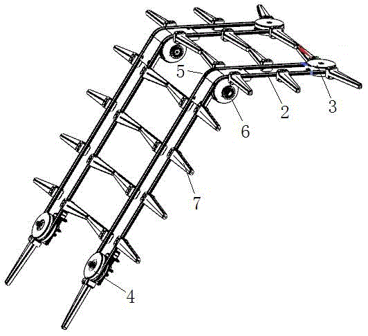
[0029] Such as Figure 1-3 As shown, the grain-holding mechanism of the harvester includes a left grain-holding mechanism, a right grain-holding mechanism and a driven pulley adjustment mechanism. Belt 2, driving pulley 3, driven pulley 4, left bending guide wheel 5 and right bending guide wheel 6. In this embodiment, the cover plate 1 is composed of an upper cover plate 11 and a lower cover plate 12. The upper surface of the upper cover plate 11 and the lower surface of the lower cover plate 12 are respectively stretched to form a groove 13. The upper cover plate 11 and the lower cover plate 12 are respectively stretched. The two sides of the groove 13 on the lower cover 12 form the running track of the finger 7, and the groove of the upper cover 11 fits with the groove of the lower cover 12 to form an installation joint 14 (that is...


PUM


Abstract

The invention discloses a plant supporting mechanism of a harvester. The plant supporting mechanism of the harvester comprises a left plant supporting mechanism body and a right plant supporting mechanism body. The left plant supporting mechanism body and the right plant supporting mechanism body respectively comprise a cover plate, an annular conveyor belt, a driving belt pulley, a driven belt pulley, a left bending guide wheel and a right bending guide wheel, wherein the annular conveyor belt, the driving belt pulley, the driven belt pulley, the left bending guide wheel and the right bending guide wheel are arranged in the cover plate; the upper portion of the cover plate is bent backward, and the left bending guide wheel and the right bending guide wheel are installed on the two sides of the position, below the bent portion, of the cover plate; the driving belt pulley is installed on the top of the cover plate, the driven belt pulley is installed at the bottom of the cover plate, the annular conveyor belt is sequentially wound around the driving belt pulley, the left bending guide wheel, the driven belt pulley and the right bending guide wheel, and a plurality of plant supporting fingers are evenly distributed on the outer circumference of the annular conveyor belt; through grooves are formed in the corresponding side walls of the left cover plate and the right cover plate respectively, and the plant supporting fingers stretch out of the through grooves of the corresponding cover plates. Through the plant supporting mechanism, the transfer and transport distance for harvested crops to enter a rotary drum can be shortened, ears entering the rotary drum are regular and orderly, a transmission chain of the combine harvester is simplified, the weight of the harvester is reduced, and energy consumption of the whole harvester is reduced.

Description

technical field [0001] The invention relates to a harvester, in particular to a harvester holding mechanism. Background technique [0002] In the original semi-feeding harvester's grain-supporting board, the chain drives the grain-supporting finger to run from top to bottom. At the upper end, there is a mechanism for folding the grain-supporting finger into the grain-supporting board. The plate lifts the grain from bottom to top, and there are many components, which is not conducive to improving the running speed and work efficiency. The original chain drives the grain-feeding finger of the grain-feeding guide to the tail below the block in the grain-feeding mechanism of the upper-mounted semi-feeding combine harvester. A section of arc track protrudes during bending operation, and the upper cover plate of the Fuhe must be constructed to accommodate this protruding arc track, which is difficult to manufacture, and is not suitable for the non-folding and extending of the Fuhe...

Claims


Application Information

Patent Timeline
Patent Type & Authority Patents(China)
IPC IPC(8): A01D65/00
Inventor 何嘉俊
Owner 何嘉俊
Why Eureka
Try Eureka