
Novel pure-metal seal joint structure

A sealing joint, pure metal technology, applied in the direction of sealing surface connection, pipe/pipe joint/pipe fitting, passing components, etc., can solve the problems of deformation, easy deformation of rubber parts, leakage, etc., and achieve broad application prospects and the effect of not being easy to wear

Inactive Publication Date: 2014-11-12
李志勇
View PDF8 Cites 5 Cited by
  • Summary
  • Abstract
  • Description
  • Claims
  • Application Information

AI Technical Summary

Problems solved by technology

[0002] Existing joint seals mostly adopt rubber seal structure, which is in the moving components and does not have anti-vibration performance. At the same time, under sandy and high-temperature climate conditions, rubber aging and wear are accelerated, which is easy to cause leakage and affect the performance of the whole machine
At the same time, the existing conical surface seals have the following disadvantages: high requirements for machining accuracy; high requirements for assembly; the conical surface is easy to scratch, and it is also easy to cause leakage; in sports equipment or machinery, it is sensitive to vibration and easy to leak; Some rubber seals have the following disadvantages: under high temperature conditions, the rubber is easy to age and deform; during the installation process, the rubber parts are also easy to deform, resulting in poor sealing

Method used


Image

  • Novel pure-metal seal joint structure
  • Novel pure-metal seal joint structure
  • Novel pure-metal seal joint structure

Examples


Embodiment 1

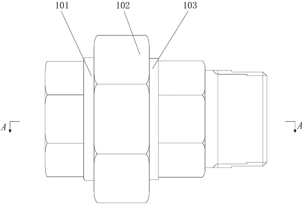
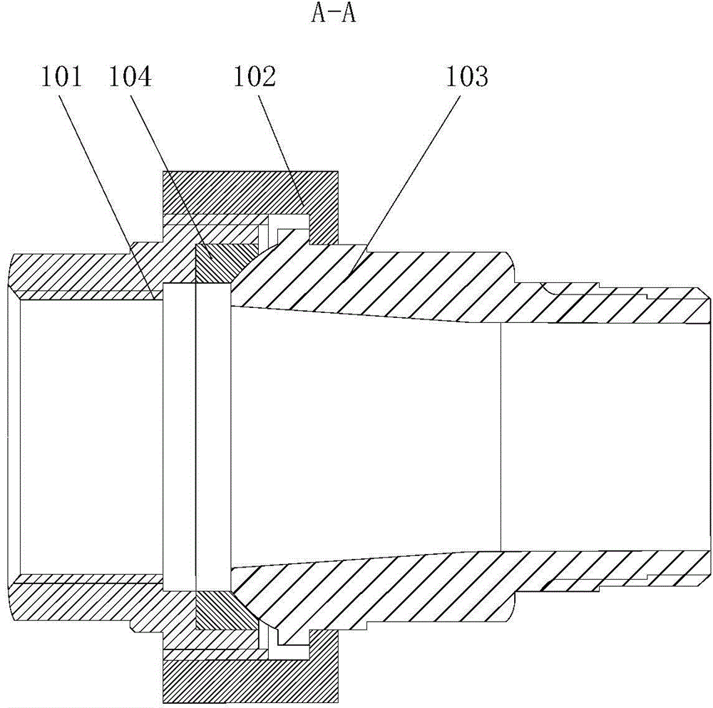
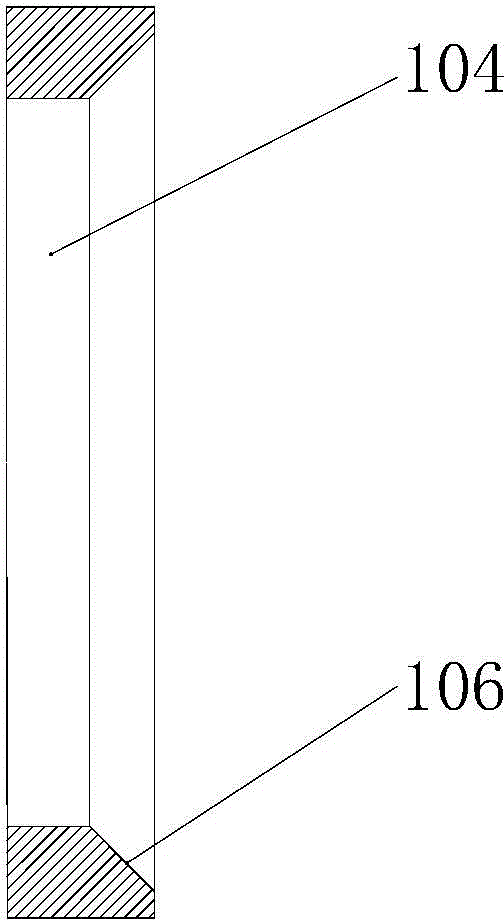
[0022] Such as Figure 1-4 As shown, a new type of pure metal sealing joint structure includes a joint A101 and a joint B103. A sealing base sleeve 104 is clamped on the inner wall of the joint A101, and a fastening nut 102 is also included for connecting the joint A101 and the joint B103. The outer walls of the joint A101 and the joint B103 are provided with threads matching the fastening nut 102, and the end of the joint B103 close to the sealing base sleeve 104 is provided with a spherical surface 105 corresponding to the sealing base sleeve 104. The joint A101, joint B103 and the sealing base sleeve 104 are both made of metal, and the hardness of the sealing base sleeve 104 is less than that of the joint B103; the joint B103 is screwed into the fastening nut 102, the sealing base sleeve 104 is installed in the joint A101, and the joint A101 is screwed into the fastening nut 102, and the fastening nut 102 is tightened so that the spherical surface 105 squeezes the sealing b...


PUM


Abstract

The invention discloses a novel pure-metal seal joint structure which comprises a joint A and a joint B. A sealing base sleeve is connected to the inner wall of the joint A in a clamped mode. The novel pure-metal seal joint structure further comprises a fastening nut. Threads matched with the fastening nut are arranged on outer walls of the joint A and the joint B, a spherical surface corresponding to the sealing base sleeve is arranged at one end close to the sealing base sleeve, of the joint B, the joint A, all of the joint B and the sealing base sleeve are made of metal, and the hardness of the sealing base sleeve is smaller than that of the joint B. The joint A and the joint B are oppositely screwed through the fastening nut to enable the spherical surface arranged on the joint B to be pressed and arranged on the sealing base sleeve in the joint A, the spherical surface arranged on the joint B extrudes the sealing base sleeve through axial fastening force of the fastening nut, and accordingly the sealing base sleeve deforms elastically. Sealing is achieved through tight and reliable connection of the spherical surface and the sealing base sleeve, the structure is not easily abraded and does not age, and deformation influencing the sealing effect does not occur.

Description

technical field [0001] The invention relates to a novel pure metal sealing joint structure. Background technique [0002] Existing joint seals mostly adopt rubber seal structure, which is in the moving components and does not have anti-vibration performance. At the same time, under sandy and high-temperature climate conditions, rubber aging and wear are accelerated, which is easy to cause leakage and affect the performance of the whole machine . At the same time, the existing conical surface seals have the following disadvantages: high requirements for machining accuracy; high requirements for assembly; the conical surface is easy to scratch, and it is also easy to cause leakage; in sports equipment or machinery, it is sensitive to vibration and easy to leak; Some rubber seals have the following disadvantages: under high temperature conditions, the rubber is easy to age and deform, etc.; during the installation process, the rubber parts are also easy to deform, resulting in...

Claims


Application Information

Patent Timeline
Patent Type & Authority Applications(China)
IPC IPC(8): F16L19/03
CPCF16L19/0212F16L19/025
Inventor 李志勇
Owner 李志勇
Learn More