Current limiting circuit

A circuit and current-limiting module technology, which is applied in the direction of adjusting electrical variables, control/regulation systems, instruments, etc., can solve the problems of large power consumption and high conduction resistance of current-limiting circuits, so as to improve accuracy, improve response speed, increase range effect

Active Publication Date: 2014-11-12
STMICROELECTRONICS (SHENZHEN) R&D CO LTD
View PDF6 Cites 5 Cited by
  • Summary
  • Abstract
  • Description
  • Claims
  • Application Information

AI Technical Summary

Problems solved by technology

[0017] even though image 3 The current limiting circuit in the circuit may accurately limit the output current of the power transistor, but the on-resistance of the current limiting circuit is very high when supplying power to the external load, so the power consumption is relatively large

Method used


Image

  • Current limiting circuit
  • Current limiting circuit
  • Current limiting circuit

Examples


Embodiment Construction

[0038] The making and using of the embodiments of the present application are discussed in detail below. It should be appreciated, however, that the present invention provides many possible innovative concepts that can be embodied in a wide variety of specific contexts. The specific embodiments discussed are merely illustrative of specific ways to make and use the application, and do not limit the scope of the application.

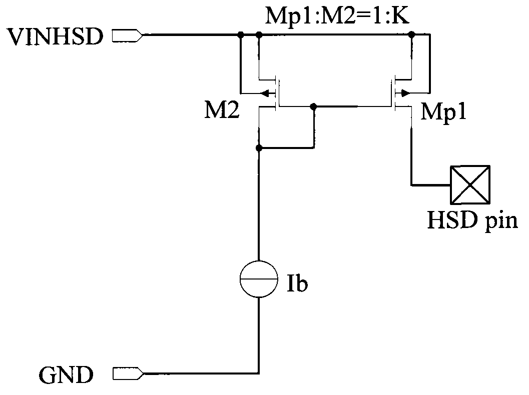
[0039] In the current limiting circuit presented below, a PMOS high-side power transistor is used as an example for description. Based on the content introduced in this application, those of ordinary skill in the art can understand how to use transistors of complementary types to construct a current limiting circuit.

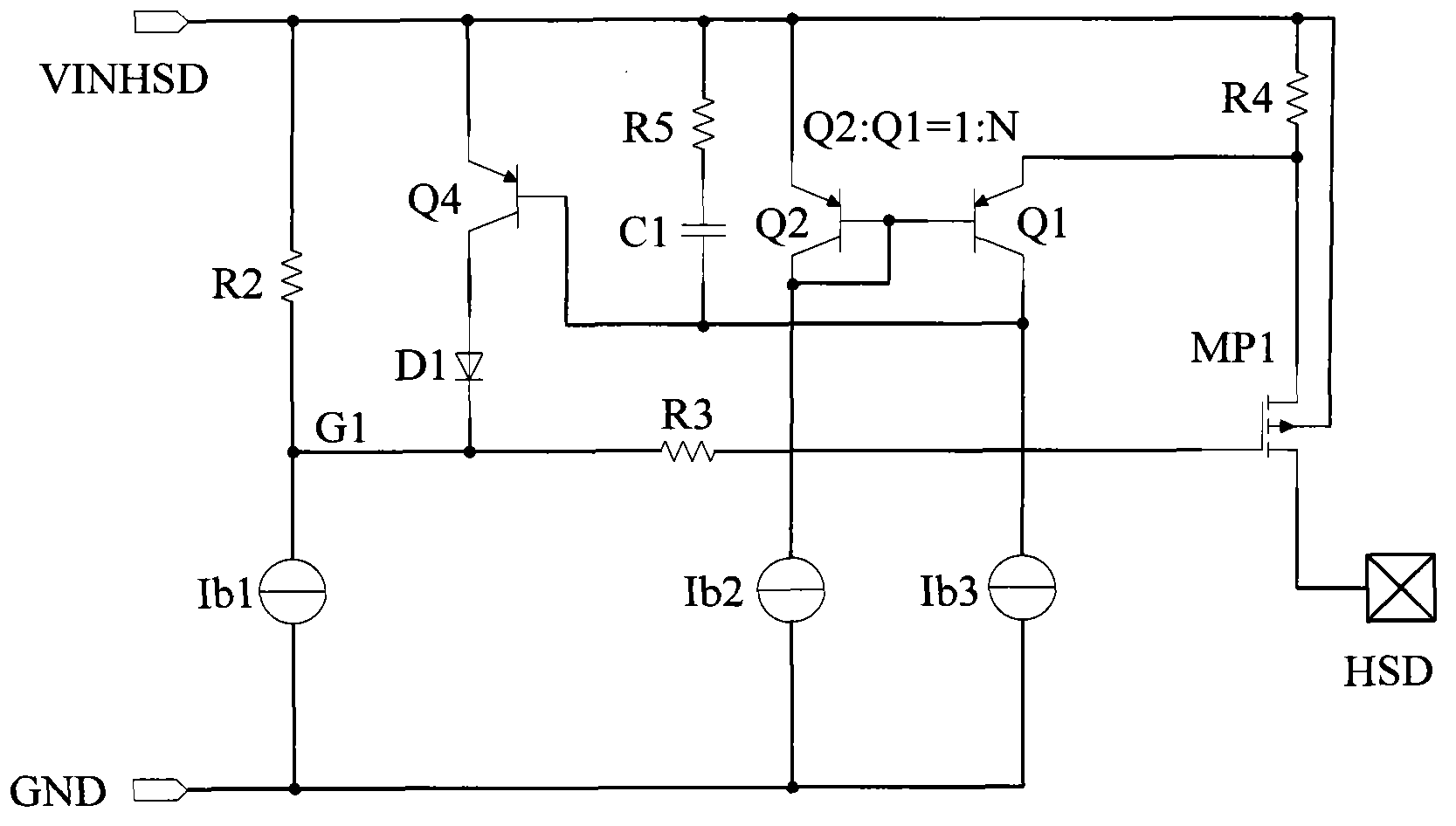
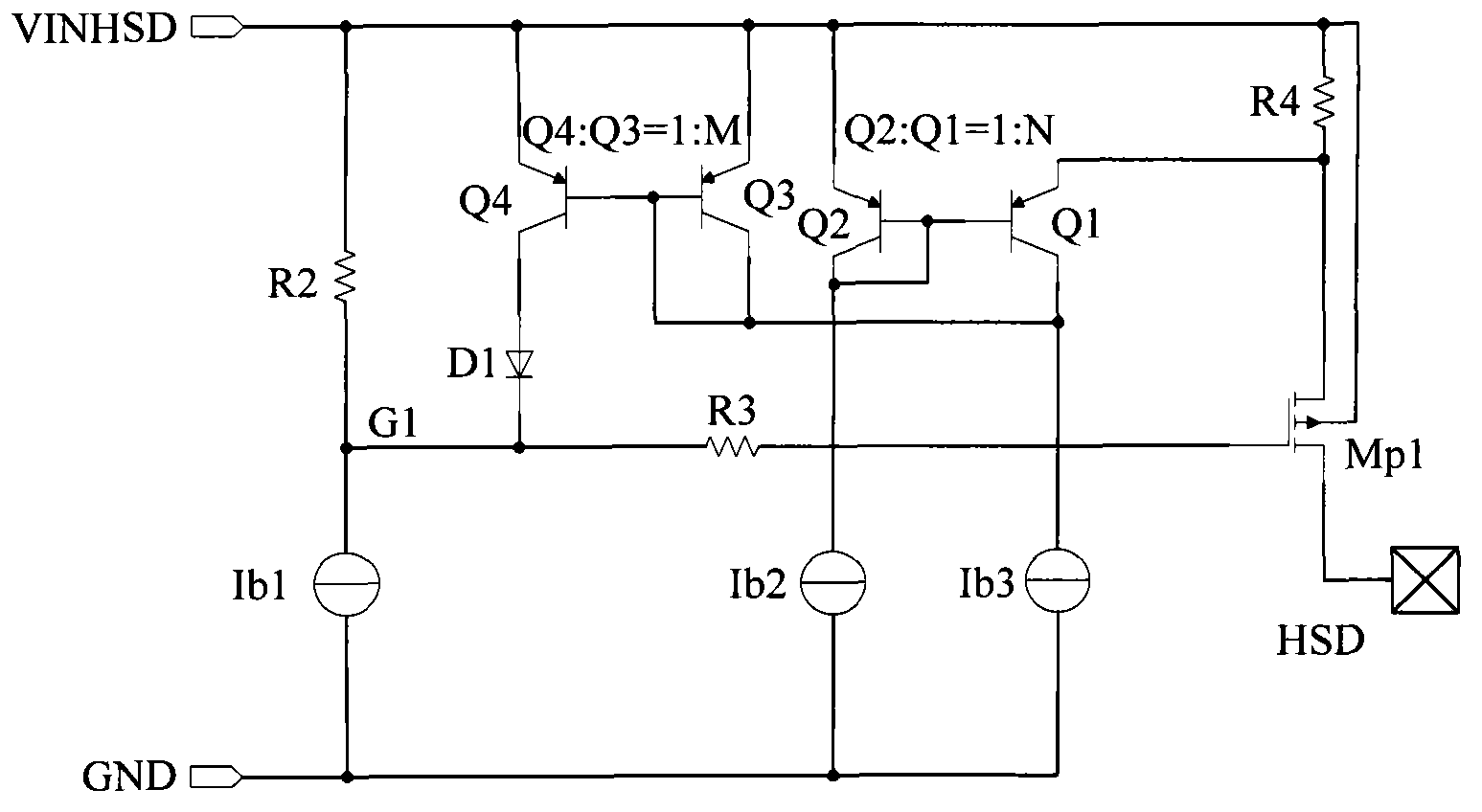
[0040] Figure 4 Shown is a current limiting circuit 100 according to one embodiment of the application. The circuit 100 may include a current sensor 20 , a low gain current limiting module 30 and / or a high gain current limiting module 40...


PUM


Abstract

A current limiting circuit includes a current sensing module that is configured to sense an output current of a power transistor and to generate a corresponding sensing current which is proportional to the output current. A first current limiting module coupled to the current sensing module is configured to generate a first limiting current based on the sensing current when a variation of the output current of the power transistor exceeds a first current level. A second current limiting module coupled to the current sensing module is configured to generate a second limiting current based on the sensing current when a variation of the output current of the power transistor exceeds a second current level. A converting module coupled to the first and second current limiting modules and the power transistor controls a gate voltage of the power transistor based at least on the first and second limiting currents.

Description

technical field [0001] The present invention relates generally to electronic circuits, and more particularly to current limiting circuits. Background technique [0002] The power circuit usually includes a high side power MOS transistor (high side power MOS transistor) and a low side power MOS transistor (low side power MOS transistor). The high-side power MOS transistor may be coupled between a power terminal for receiving a power supply voltage and an output terminal for providing the power supply voltage to an external load. A low-side MOS transistor may be coupled between the output terminal and a reference terminal for receiving a reference voltage, wherein the reference voltage is lower than the supply voltage. These two power MOS transistors can be turned on or off to selectively provide power supply voltage to external loads. [0003] Inductive external loads require a stable output to avoid oscillations. Therefore, the current limiting circuit is widely used to l...

Claims


Application Information

Patent Timeline
IPC IPC(8): G05F1/56
CPCG05F1/573
Inventor 曾妮
Owner STMICROELECTRONICS (SHENZHEN) R&D CO LTD
Why Eureka
Try Eureka