Sintering device for super-miniature annular voltage dependent resistors

A varistor, sintering device technology, applied in resistors, resistor manufacturing, circuits, etc., can solve the problem of ultra-miniature ring varistor semiconducting into electronic ceramics, mechanical strength, electrical properties can not meet the requirements, metallization degree difference and other issues, to achieve the effect of light weight, low heat storage performance, and long service life

Active Publication Date: 2014-11-12
GUANGDONG FENGHUA ADVANCED TECH HLDG
View PDF5 Cites 5 Cited by
  • Summary
  • Abstract
  • Description
  • Claims
  • Application Information

AI Technical Summary

Problems solved by technology

When the material is sintered with hydrogen, a reduction reaction will occur to form a metal substance. The reaction is gradually carried out from the surface of the blank ring to the center of the blank ring; Fully exposed to the hydrogen in the furnace body, the synchronous reduction reaction will cause differences in the metallization degree of each blank ring and different parts of the same blank ring, resulting in poor semiconducting of the blank ring of the ultra-miniature ring varistor into electronic ceramics. Deformation occurs, so that the mechanical strength and electrical properties cannot meet the requirements

Method used


Image

  • Sintering device for super-miniature annular voltage dependent resistors
  • Sintering device for super-miniature annular voltage dependent resistors
  • Sintering device for super-miniature annular voltage dependent resistors

Examples


Embodiment Construction

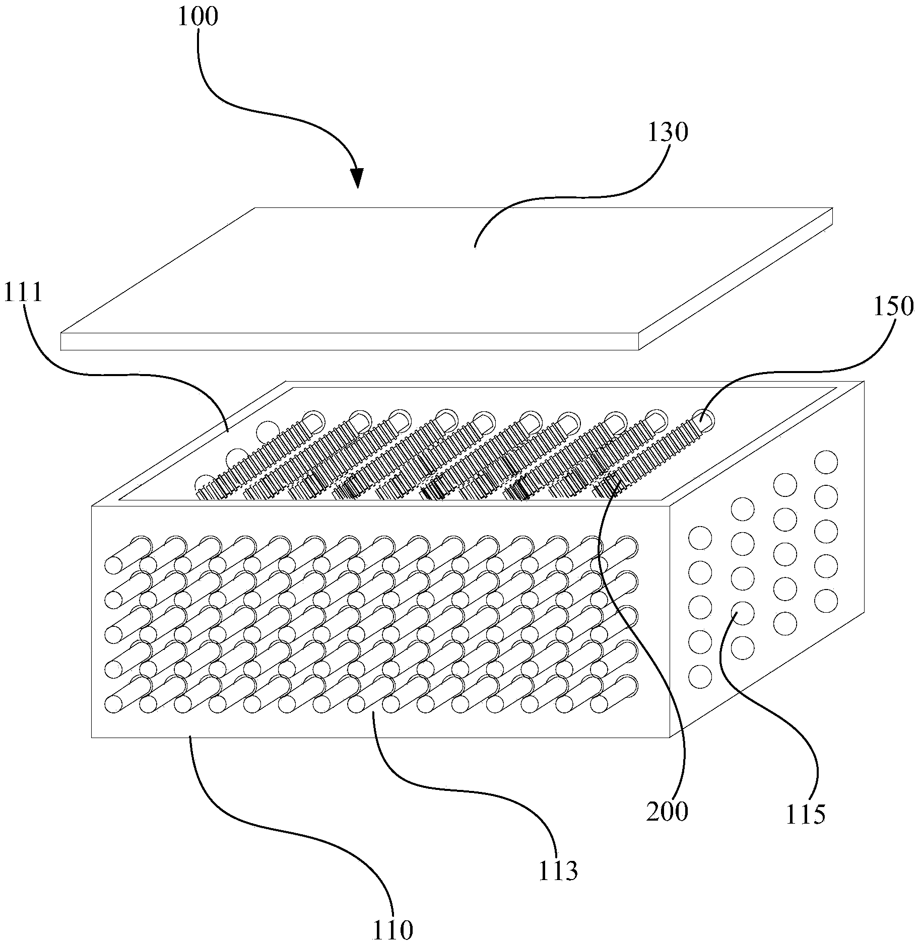
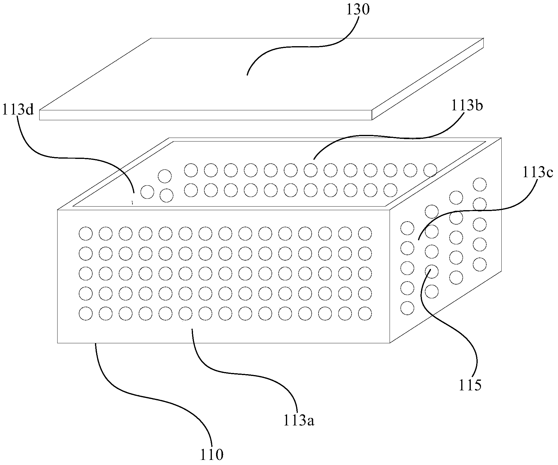
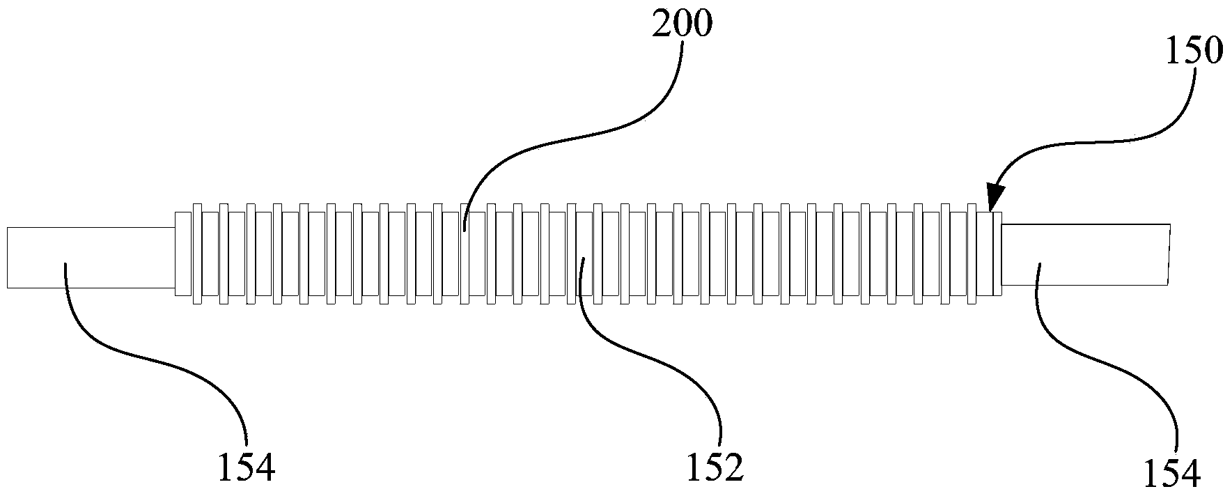
[0027] In order to facilitate the understanding of the present invention, the present invention will be described more fully below with reference to the relevant drawings. The preferred embodiments of the present invention are shown in the drawings. However, the present invention can be implemented in many different forms and is not limited to the embodiments described herein. On the contrary, the purpose of providing these embodiments is to make the disclosure of the present invention more thorough and comprehensive.

[0028] It should be noted that when an element is referred to as being "fixed to" another element, it can be directly on the other element or a central element may also exist. When an element is considered to be "connected" to another element, it can be directly connected to the other element or an intermediate element may be present at the same time. The terms "vertical", "horizontal", "left", "right" and similar expressions used herein are for illustrative pur...


PUM


Abstract

The invention relates to a sintering device for super-miniature annular voltage dependent resistors. The sintering device for the super-miniature annular voltage dependent resistors comprises a bottom shell, a cover body and a plurality of sintering bars. The bottom shell comprises a bottom wall and a plurality of side walls surrounding the bottom wall. The bottom shell is provided with the open end opposite to the bottom wall. The side walls are provided with a plurality of air holes. The cover body detachably covers the open end. The shell and the cover body together form a containing cavity. The sintering bars are contained in the containing cavity, horizontally hung and arranged between the two opposite side walls of the bottom shell. The sintering bars are used for being arranged in through holes in the middle of blank rings of the multiple super-miniature annular voltage dependent resistors in a penetrating mode so that the multiple blank rings can be hung on the sintering bars at intervals. According to the sintering device for the super-miniature annular voltage dependent resistors, the blank rings are not prone to deforming in the sintering process, and the requirements for the mechanical strength and the electrical property of the super-miniature annular voltage dependent resistors are met.

Description

Technical field [0001] The invention relates to semiconductor manufacturing technology, in particular to a sintering device for an ultra-miniature annular varistor. Background technique [0002] Ring varistor is a sensitive component with nonlinear volt-ampere characteristics. Under normal voltage conditions, this is equivalent to a small capacitor, and when an overvoltage occurs in the circuit, its resistance drops sharply and quickly turns on, its working current increases by several orders of magnitude, and the resistance value of the varistor is added to the outside. The voltage change effectively protects other components in the parallel circuit from overvoltage and damages and suppresses the peak value of the loop voltage within a certain range. [0003] At present, we call the ring varistor with an outer diameter of less than 2.4mm as "ultra-mini ring varistor". This is a ring varistor with the smallest size at present, its size is (outer diameter * inner diameter * thickn...

Claims


Application Information

Patent Timeline
Patent Type & Authority Applications(China)
IPC IPC(8): H01C17/30
Inventor 张振勇邓佩佳夏颖梅
Owner GUANGDONG FENGHUA ADVANCED TECH HLDG
Why Eureka
Try Eureka