Control valve for an air spring and motor vehicle seat having a control valve

A technology for pneumatic springs and vehicle seats, which is applied to vehicle seats, vehicle components, seat suspensions, etc., and can solve the problems of height adjustment devices, such as the fineness of static height adjustment and the response performance of sensitivity and speed are not optimal. , to achieve the effect of reducing tolerance, avoiding empty travel and precise control

Active Publication Date: 2014-11-12
GEBR ISRINGHAUSEN GMBH & CO KG
View PDF7 Cites 2 Cited by
  • Summary
  • Abstract
  • Description
  • Claims
  • Application Information

AI Technical Summary

Problems solved by technology

However, in such valve arrangements, the responsiveness of the height adjustment device is not optimal with regard to the fineness and sensitivity and speed of the static height adjustment

Method used


Image

  • Control valve for an air spring and motor vehicle seat having a control valve
  • Control valve for an air spring and motor vehicle seat having a control valve
  • Control valve for an air spring and motor vehicle seat having a control valve

Examples


Embodiment Construction

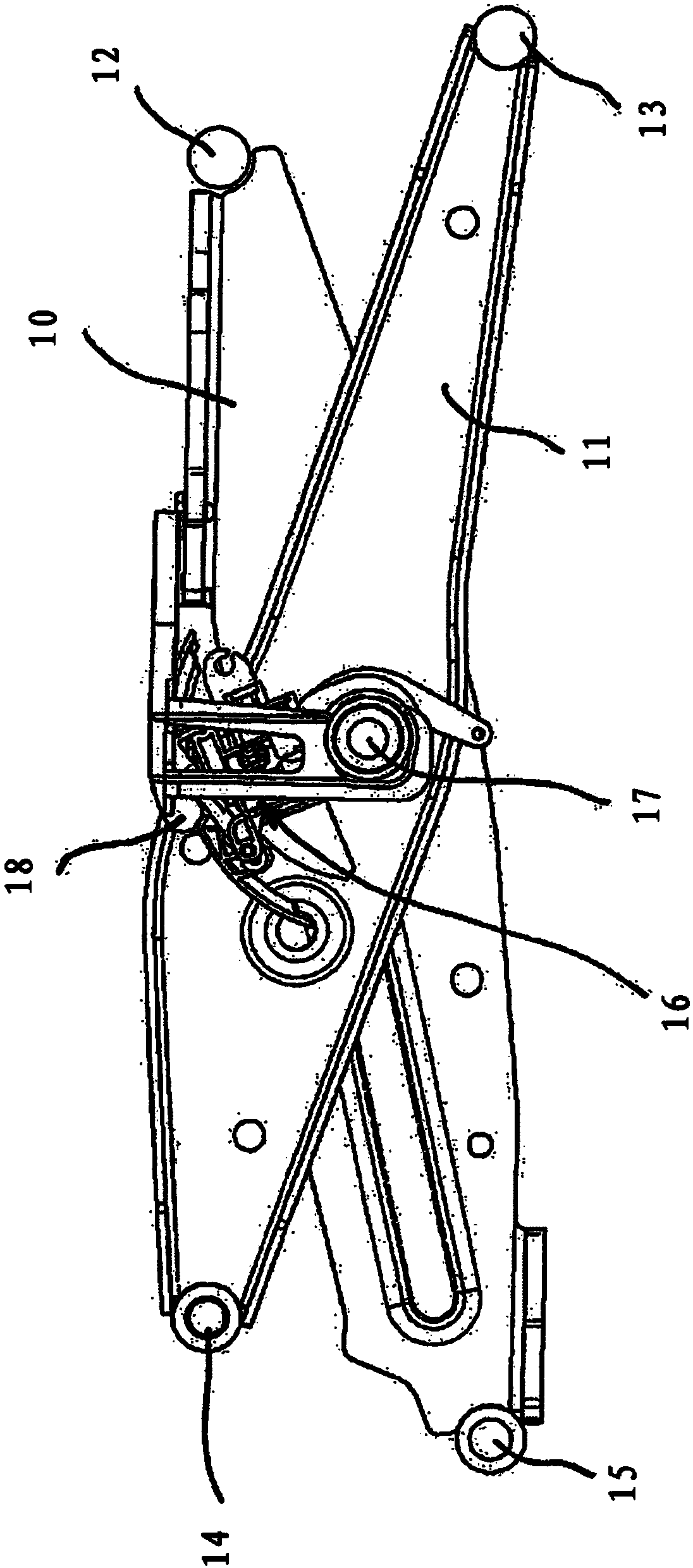
[0026] exist figure 1 A side view of part of the swing system of a vehicle seat showing a pneumatic spring. Furthermore, the theoretical design of such a pivoting system with a height adjustment device of a seat surface of a vehicle seat or a height adjustment device is known in principle. Therefore, only the components that are relevant to the design of the invention will be considered below.

[0027] figure 1 Two scissor link pairs arranged parallel to one another are shown with an inner scissor link 10 and an outer scissor link 11 . The two scissor links 10 , 11 are rotatably connected to each other via a shaft 17 . The scissor guide rod in its figure 1 On the right-hand ends shown in , there are respectively fixed bearings 12 , 13 , which are fixed in position on the upper frame (not shown) or the lower frame (likewise not shown). Horizontal displacement bearings 14 , 15 are formed at the respective left-hand ends of the scissor links 10 , 11 . It is possible to adju...


PUM


Abstract

The invention relates to a control valve (16) for an air spring, comprising a housing (41), an exhaust duct that has an exhaust tappet (26) for opening of closing the exhaust duct, which exhaust tappet interacts with a first control means (19), a ventilation duct that has a ventilation tappet (27) for opening or closing the ventilation duct, which ventilation tappet interacts with a second control means (20), and a supplemental duct having a supplemental tappet (28) for opening or closing the supplemental duct, which supplemental tappet interacts with a third control means (21), wherein a first air connection A connects to the exhaust duct and a second air connection P connects to the exhaust duct together with the supplemental duct, wherein a first control means (19) and a second control means (20) are arranged to one another in such a manner that said control means cannot be actuated at the same time by an control element (18), and wherein the second control means (20) and the third control means (21) are arranged to one another in such a manner that the supplemental duct can only be opened when the ventilation duct is opened. The invention further relates to a motor vehicle seat comprising a mechanical swing system and an air spring, which motor vehicle seat has such a control valve.

Description

technical field [0001] The invention relates to a control valve for a pneumatic spring and a vehicle seat with a mechanical pivot system and a pneumatic spring with a control valve. Background technique [0002] Vehicle seats are known in commercial vehicles which are equipped with a pivotable and height-adjustable scissor pivot system. This scissor swing system consists of at least one pneumatic spring and pair of scissor guide rods. The scissor links are pivotably arranged relative to one another by means of a common shear axis. The control unit is used for height adjustment and height adjustment of the scissor swing system. The control device includes a control valve for controlling the inflation and deflation process of the pneumatic spring. The control valve is operated by a follower pin which acts on a control rod arranged on the control valve. The height adjustment device has an integrated height adjustment device for maintaining the center position of the pivotin...

Claims


Application Information

Patent Timeline
Patent Type & Authority Applications(China)
IPC IPC(8): B60N2/50B60N2/52
CPCB60N2/525B60N2/508B60N2/501B60N2/502B60N2/505B60N2/0224B60N2/1665F16K17/363F16K31/602
Inventor 赖纳·利克尔
Owner GEBR ISRINGHAUSEN GMBH & CO KG
Why Eureka
Try Eureka