Plastic bag packing machine
A technology of plastic bags and packaging machines, applied in packaging and other directions, can solve problems such as difficulty in adapting to the speed of bag making machines
- Summary
- Abstract
- Description
- Claims
- Application Information
AI Technical Summary
Problems solved by technology
Method used
Image
Examples
Embodiment 1
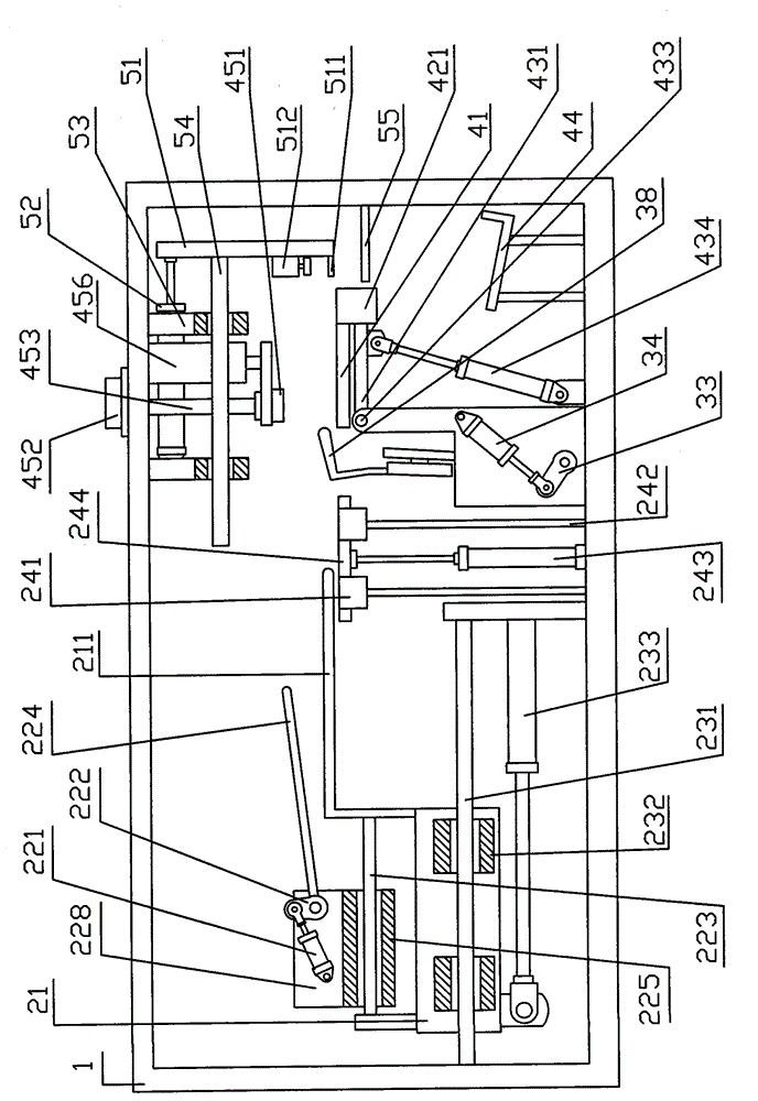
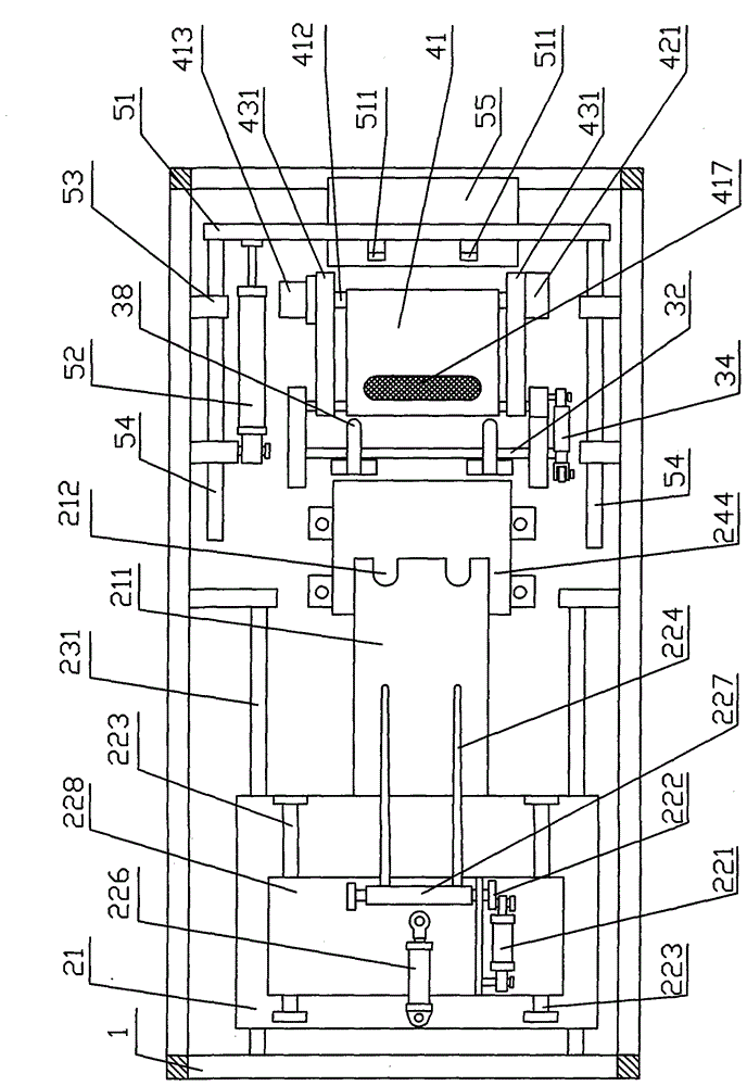
[0051] Embodiment 1: as figure 1 , figure 2 , Figure 5 , Figure 7 , Figure 8 , Figure 17 shown. The plastic bag packaging machine comprises a frame 1 and a manipulator conveying device 8 . On the frame 1, there are sequentially arranged from the front to the rear: a folding and loading device 2, a support plate swing mechanism 3, a swing type bag taking and opening device 4, and a clamping output device 5.
[0052] The front portion (the left side of accompanying drawing) of frame 1 is installed in half and folds into device 2. The half-folding device 2 includes: a push-fold bracket 21 , a push-fold plate 211 , a pressing bar mechanism 22 , a push-fold movement mechanism 23 , and a half-fold mechanism 24 . Depression bar mechanism 22 comprises: lifting pressure cylinder 221, rocking arm 222, guide rail 223, depression bar 224 slide block 225, cylinder 226, depression bar rotating shaft 227, depression bar bracket 228; , slide block 232, pushing and folding cylinde...
Embodiment 2
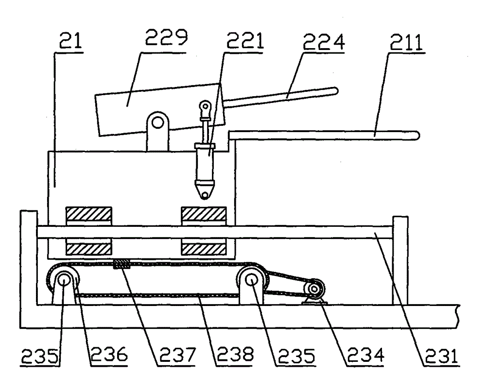
[0068] Embodiment 2: as image 3 , Figure 4 , Image 6 , Figure 9 Shown: the difference between embodiment 2 and embodiment 1 is mainly in the pressing rod mechanism 22 of the folding and loading device 2, the pushing and folding plate moving mechanism 23; , Swing device 42, lifting mechanism 43, opening mechanism 45; The output motion mechanism of clamping output device 5.
[0069] A push rod cylinder 227 is installed in the middle of the top of the push and folded plate bracket 21, and the cylinder rod of the push rod cylinder 227 is exactly the push rod 224, and the cylinder middle part of the push rod cylinder 227 is hinged on the pushed and folded plate bracket 21; One end of the rod cylinder 227 is connected with the lifting and pressing cylinder 221 , and the other end of the lifting and pressing cylinder 221 is installed on the bracket 21 of the pushing and folding plate.
[0070] Rotate and install two mutually parallel power transmission shafts 235 on both side...
Embodiment 3
[0081] Embodiment 3: This embodiment is based on Embodiment 1 and Embodiment 2, omitting the lifting pallet. Concrete working process is: in the process of conveying plastic bag 6, when the first half of plastic bag arrives on the top of pushing plate 211, manipulator conveying device 8 stays, when pressing bar 224 stretches out and pushes down plastic bag 6, like Figure 17 Under the state shown, manipulator conveying device 8 is unclamped and continues to move backward certain distance and plastic bag 6 is put down, and the first half of plastic bag 6 rides on the pushing and folding plate 211 at this moment, and its second half hangs down because there is no support , fold the middle of the plastic bag 6 into a right angle to form as Figure 18 status shown.
PUM
 Abstract
Description
Claims
Application Information
 - R&D
- Intellectual Property
- Life Sciences
- Materials
- Tech Scout
- Unparalleled Data Quality
- Higher Quality Content
- 60% Fewer Hallucinations
Browse by: Latest US Patents, China's latest patents, Technical Efficacy Thesaurus, Application Domain, Technology Topic, Popular Technical Reports.
© 2025 PatSnap. All rights reserved.Legal|Privacy policy|Modern Slavery Act Transparency Statement|Sitemap|About US| Contact US: help@patsnap.com


