A device and method for connecting shear walls and concrete floors in building structures

A technology for building structures and shear walls, applied in building structures, buildings, etc., can solve the problems of large workload, reduced bearing capacity, low concrete strength, etc., and achieves small manual workload, small welding workload, and time-consuming less effect

Active Publication Date: 2016-07-20
ARCHITECTURAL DESIGN & RES INST OF SOUTH CHINA UNIV OF TECH
View PDF9 Cites 1 Cited by
  • Summary
  • Abstract
  • Description
  • Claims
  • Application Information

AI Technical Summary

Problems solved by technology

This approach faces a problem: the formwork 5 set when pouring the shear wall 1 will always cross the height of the concrete floor 2, and the connecting steel bar 4 that is reserved in the shear wall 1 to be connected to the concrete floor 2 will hinder the setting of template 5
Adopt this method and can run into three problems: (1) because the number of connecting steel bars 4 is large, and the cost of chemically planting bars is relatively high, so the economy is not good and the workload is large; (2) the number of steel bars in the shear wall 1 Also a lot, drilling in the side wall of the shear wall 1 that has been poured, often encounters the steel bar in the wall and has to be re-drilled in a different position, eventually causing the surface of the shear wall 1 to be full of holes; (3) new The strength of hardened concrete is still relatively low, so intensive drilling will cause many cracks inside the shear wall 1, reducing its bearing capacity
Since the existing construction methods have been used for many years and the operation methods are relatively familiar, it is difficult for technicians to get out of the shackles of the existing technology

Method used


Image

  • A device and method for connecting shear walls and concrete floors in building structures
  • A device and method for connecting shear walls and concrete floors in building structures
  • A device and method for connecting shear walls and concrete floors in building structures

Examples


Embodiment

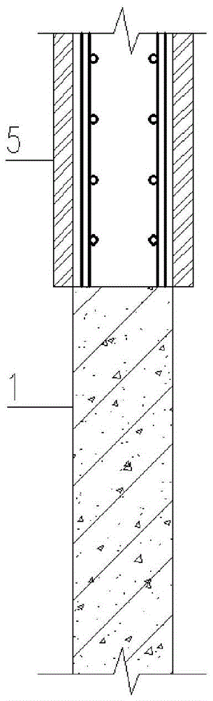
[0059] The structural design of a high-rise building has a total of 60 floors and a total height of more than 250 meters. The frame-core tube structure system is adopted, that is, the core tube is composed of 4 closed shear walls 1 in the central area of ​​the building, and the thickness of the shear wall 1 is selected For: the wall thickness of the 1st to 10th floors is 1000mm; The thickness of the 60-layer wall is 500mm.

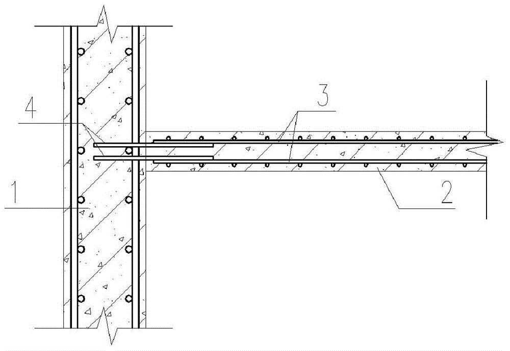
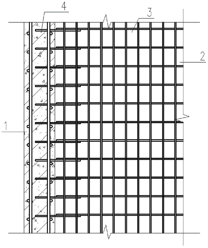
[0060] The length of the four shear walls 1 forming the core tube is 25m in the horizontal direction, and frame columns 9 are arranged around the core tube, as shown in Figure 8 shown. The thickness of the concrete floor 2 is 110mm, and the steel bar 3 pointing to the shear wall 1 in the slab adopts the design strength f 2 = 360MPa tertiary steel bar, set on the slab surface and the slab bottom, the diameter of the steel bar 3 inside the slab is 10mm, and the spacing is 100mm.

[0061] According to the construction sequence, the shear wall 1 of the cor...


PUM


Abstract

The invention discloses a device for connecting a shear wall and a concrete floor in a construction structure and an arranging method thereof. The device is composed of multiple anchor bars, a vertical anchor plate and a U-shaped toothed part, wherein one end of each anchor bar is fixed to the inner surface of the vertical anchor plate, the other end of each anchor bar stretches into the shear wall, one end of the U-shaped toothed part is fixed to the outer surface of the vertical anchor plate, the highest position of the U-shaped toothed part is located in the middle of the concrete floor in the thickness direction, a horizontal plate is arranged below the U-shaped toothed part, vertical plates provided with rectangular teeth are arranged on the two sides of the U-shaped toothed part, and the product of the total cross section of the anchor bars and the material strength of the anchor bars is not smaller than the product of the total cross section of intra-plate bars, facing the shear wall, in the concrete floor and the material strength of the intra-plate bars. According to the device and method, connecting bars arranged in the shear wall and connected with the concrete floor in the prior art are replaced, reinforcing bar arrangement work during shear wall and concrete floor construction is simplified, damage to the shear wall according to the current construction technology is avoided, and construction period can be shortened.

Description

technical field [0001] The invention relates to a connection device for connecting a shear wall and a concrete floor in a building structure and a setting method thereof, belonging to the field of construction engineering. Background technique [0002] Shear walls and concrete slabs (concrete slabs include roof slabs in the present invention) are very widely used components in building structures. Shear walls are generally installed vertically to resist horizontal actions (such as wind, horizontal earthquakes, etc.) on the building structure, and also bear vertical loads (such as the self-weight of the building, service load, etc.). Concrete slabs are generally set horizontally to bear vertical loads, and also coordinate the deformation of all vertical members on the same floor through horizontal shear stiffness. [0003] A reliable connection should be set up between the shear wall and the concrete floor to ensure the coordinated deformation of the two in the horizontal di...

Claims


Application Information

Patent Timeline
Patent Type & Authority Patents(China)
IPC IPC(8): E04B1/61E04B1/41
Inventor 王帆莫盛浩罗志锋
Owner ARCHITECTURAL DESIGN & RES INST OF SOUTH CHINA UNIV OF TECH
Why Eureka
Try Eureka