
Semi-wedge type roller

A drum and wedge-type technology, applied in the field of wedge-cut drums, can solve the problem of low lump coal rate in the drum, and achieve the effects of dust reduction, cost reduction, and coal production cost reduction

Inactive Publication Date: 2014-11-19
郑涛
View PDF9 Cites 6 Cited by
  • Summary
  • Abstract
  • Description
  • Claims
  • Application Information

AI Technical Summary

Problems solved by technology

[0003] In order to solve the problem of low lump coal rate of the widely used drums, the present invention adopts a new coal cutting principle to form a wedge-cutting drum

Method used


Image

  • Semi-wedge type roller

Examples


Embodiment Construction

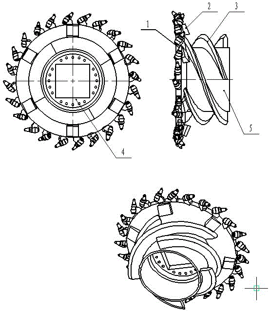
[0019] Referring to the accompanying drawings, the cutting disk 1 is welded together with the spiral blade 3, the coupling disk 4, and the cylinder hub 5, and picks are arranged on the outer edge of the cutting disk 1. In order to ensure that the coal in the opened groove can be discharged smoothly, and the two grooves The groove width should be about 200mm (the specific size should be adjusted according to the diameter of the cutting disc 1) so as not to rub against the tooth seat. The wedge 2 is placed between the outer edge of the cutting disc 1 and the spiral blade 3. The outer surface is a space slope, and the direction of inclination should correspond to the direction of rotation of the drum. During operation, the wedge will wedge into the cutting disc 1 as the shearer travels. The trench that is opened, and rely on the thrust of the shearer to walk and the force of the drum rotation to split the coal wedge on the outside of the trench, so the wedge 2 will be mad...


PUM


Abstract

The invention relates to a semi-wedge type roller applied in coal cutter of coal mining equipment. In order to improve the block coal rate, a novel coal cutting theory and structure are adopted. The semi-wedge type roller is different from the conventional rollers mainly in three parts: the cutting disc (1), the wedge block (2), and the spiral blade (3). The cutting disc (1) is similar to the end plate in the conventional rollers and is used to dig a groove on the coal wall. The external surface of the wedge block (2) is a spacial inclined plane, the wedge block (2) is inserted into the groove as the coal cutter is moving forward, and the coal on the external side of the groove is cut off through the movement of the coal cutter and the rotation of the roller. The external edge of the spiral blade is in a shape angle shape and is not provided with any cutting pick, the spiral blade (3) is mainly used to store coals, and when the coals are not cut off, the sharp angle of the external edge of the spiral blade (3) will cut off the coals to assist the coal cutting.

Description

technical field [0001] The invention relates to a wedge-cutting drum used for a coal shearer in coal mine equipment. Background technique [0002] For a long time, the drums used by coal shearers have been equipped with picks on the entire cutting depth of the drum, that is, picks are installed on the end disk and the spiral blade. The coal on the coal wall is cut off by the shearer walking and the drum rotating. Although the picks on the drum are arranged in different ways, their intercept line distances are all between 30-50mm, which causes the cut coal to be too broken. Especially the coal near the coal wall will be repeatedly broken by the picks on the helical blade during the process of being pushed to the scraper conveyor by the helical blade after cutting, resulting in an extremely low lump coal rate. In order to increase the lump coal rate, some manufacturers have designed a large coal drum. The principle is to increase the intercept distance on the basis of the or...

Claims


Application Information

Patent Timeline
IPC IPC(8): E21C25/10
Inventor 郑涛郑克玄
Owner 郑涛
Learn More