Contactor

A contactor and contact part technology, applied in relays, electromagnetic relays, electromagnetic relay detailed information, etc., can solve the problems of difficult to achieve automatic assembly, low production efficiency, troublesome winding, etc., to facilitate automatic assembly, improve production efficiency, The effect of reducing production costs

Active Publication Date: 2014-11-19
XIAMEN HONGFA ELECTRICAL SAFETY & CONTROLS CO LTD
View PDF4 Cites 4 Cited by
  • Summary
  • Abstract
  • Description
  • Claims
  • Application Information

AI Technical Summary

Problems solved by technology

[0003] First, there are many plastic components in the contactor in the prior art, usually 6 to 10 or even more, which makes the structure more complicated, the cost of injection molding is higher, it is difficult to assemble automatically, and the protection level is lower;
[0004] Second, when the conductive sheet is connected to the coil, two terminals of the same height are usually formed at intervals on the conductive sheet, and the two terminals set at the same height make the coil winding wires prone to interference during winding, making winding more troublesome and affecting production Efficiency; during automatic assembly of conductive sheets with two terminals set at equal heights, there is a large gap between the two terminals of one conductive sheet and the adjacent conductive sheet, so that when the conductive sheet is transported on the production line, the distance between the adjacent con

Method used


Image

  • Contactor
  • Contactor
  • Contactor

Examples


Embodiment Construction

[0052] The present invention will be described in detail below in conjunction with the accompanying drawings and specific embodiments.

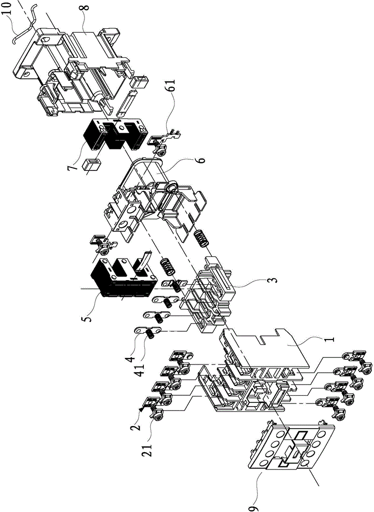
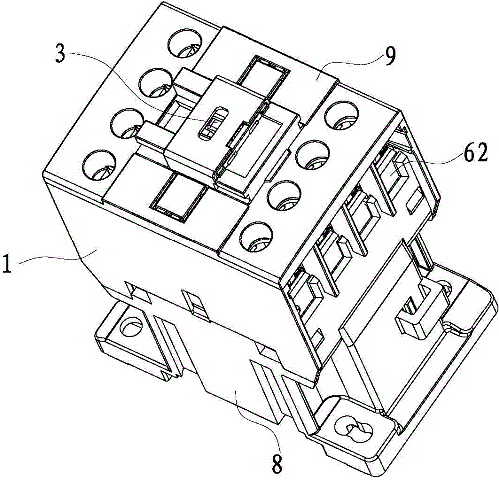
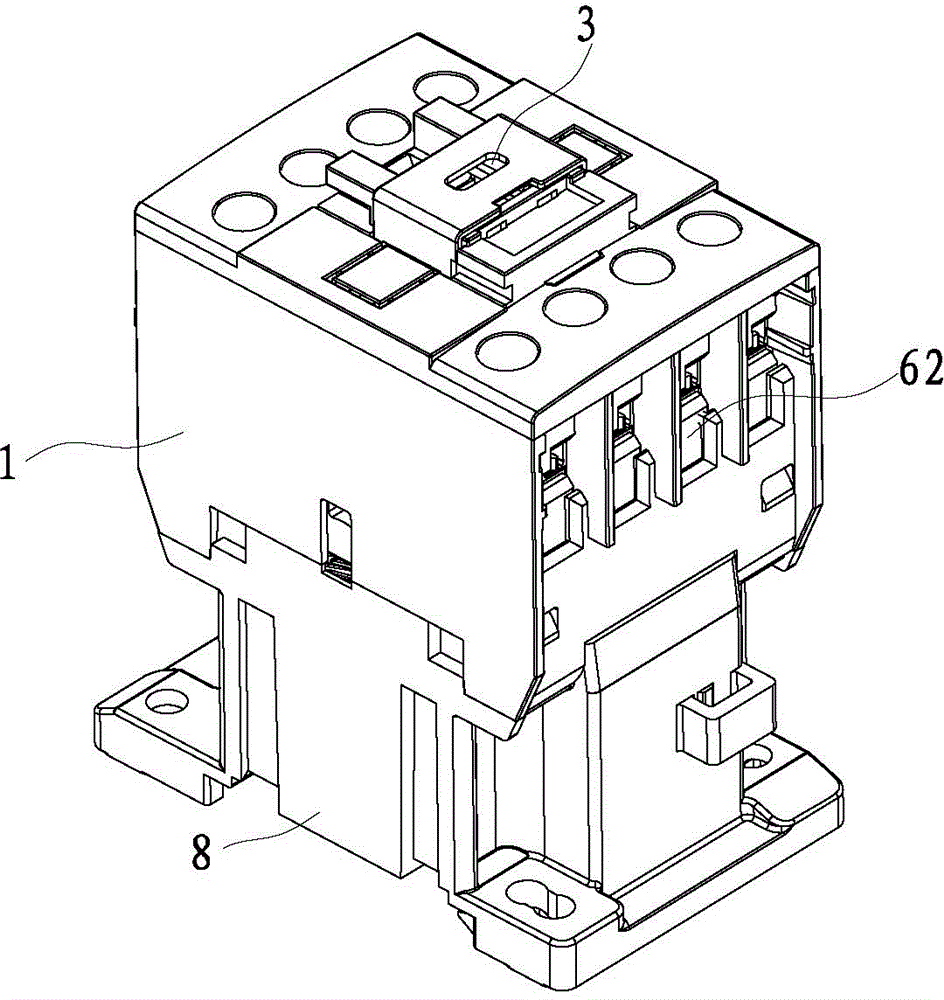
[0053] refer to Figure 1 to Figure 20 As shown, a contactor disclosed by the present invention includes a body 1, a static contact 2, a contact support 3, a moving contact 4, a moving iron core 5, a bobbin 6, a static iron core 7, a base 8 and a cover 9.

[0054] The contact support 3 is movably installed in the body 1, the coil bobbin 6 is placed in the base 8, and inserted into the body 1, and the body 1 is installed on the base; the integrated cover 9 with IP2X protection level is installed on the body 1.

[0055] Such as Figure 18 and Figure 19 As shown, a hollow part 91 is formed on the cover 9, and the hollow part 91 is used for the contact support 3 of the contactor to be exposed to the cover 9 to partially accommodate it. At the same time, two sets of functional auxiliary modules can also be installed on the hollow part 91. The...


PUM


Abstract

The invention discloses a contactor. The contactor comprises a shell, a contact terminal support, a coil framework, a base and a cover cap, wherein the contact terminal support is movably mounted inside the shell; the coil framework is placed in the base, and is inserted into the shell; the shell is mounted on the base; the cover cap that is provided with the IP2X protection level and is integrally formed is mounted on the shell. The contactor is simple in structure, relatively high in protection level, firm and stable in wiring, and suitable for automatic assembly.

Description

technical field [0001] The invention relates to a contactor. Background technique [0002] In the prior art, a contactor generally includes a body, a static contact, a contact support, a moving contact, a moving iron core, a coil bobbin, a static iron core, and a base; wherein, the static contact is installed in the body, and the moving contact is installed In the contact support, the static contact is usually inserted into the body, and at the same time, the moving iron core is installed on the contact support and placed in the coil frame; the static iron core is installed in the base, and the coil frame is installed on the body, juxtaposed In the base, the static iron core is embedded in the coil frame; the conductive sheet is installed on the coil frame, and the conductive sheet is connected with the coil on the coil frame. However, the disadvantages of prior art contactors are: [0003] First, there are many plastic components in the contactor in the prior art, usually...

Claims


Application Information

Patent Timeline
IPC IPC(8): H01H50/04H01H50/14
Inventor 田新疆夏昌慧
Owner XIAMEN HONGFA ELECTRICAL SAFETY & CONTROLS CO LTD
Why Eureka
Try Eureka