Touch switch control circuit of fading type delay lamp

A touch switch, control circuit technology, applied in the direction of electric lamp circuit layout, electric light source, lighting device, etc., can solve the problems of sound and light sensor lamp noise wake-up, noise pollution, blindness of eyes, etc., to achieve easy replacement, change delay time, structure simple effect

Inactive Publication Date: 2014-11-19
张小亚
View PDF3 Cites 3 Cited by
  • Summary
  • Abstract
  • Description
  • Claims
  • Application Information

AI Technical Summary

Problems solved by technology

[0002] With the development of society and the advancement of science and technology, the degree of development of a city can be measured to a certain extent by the penetration rate of lights in the city at night. At the same time, for the safety of people walking, street lights are installed in residential corridors, but Due to the aggravation of noise pollution in the city, the sound and light sensor lights installed in the residential corridors are often awakened by the noise, resulting in a waste of power resources. At the same time, the sudden on and off of the lights will cause temporary blindness to the eyes.

Method used


Image

  • Touch switch control circuit of fading type delay lamp

Examples


Embodiment Construction

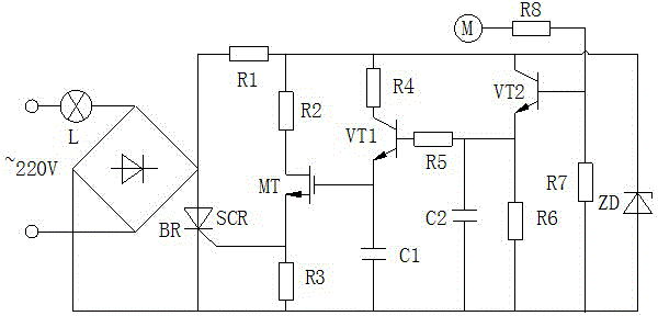
[0009] The present invention will be further described below in conjunction with accompanying drawing:

[0010] like figure 1 As shown, the touch switch control circuit of the dimming delay lamp in the present invention includes the first resistor R1 to the eighth resistor R8, the first capacitor C1, the second capacitor C2, the first triode VT1, and the second triode VT2 , field effect transistor MT, thyristor SCR, Zener diode ZD, touch electrode sheet M, bridge rectifier circuit BR and lamp L, the first end of lamp L is connected to the positive pole of the mains, and the second end of lamp L is connected to the bridge rectifier The first AC input terminal of the circuit BR is connected, the second AC input terminal of the bridge rectifier circuit BR is connected to the negative pole of the mains, the positive output terminal of the bridge rectifier circuit BR is respectively connected to the first terminal of the first resistor R1 and the thyristor SCR Positive connection,...


PUM


Abstract

The invention discloses a touch switch control circuit of a fading type delay lamp. The touch switch control circuit comprises a first resistor, a second resistor, a third resistor, a fourth resistor, a fifth resistor, a sixth resistor, a seventh resistor, an eighth resistor, a first capacitor, a second capacitor, a first triode, a second triode, a field-effect transistor, a thyristor, a voltage stabilizing diode, a touch electrode plate, a bridge rectifier circuit and the lamp. According to the touch switch control circuit of the fading type delay lamp, when the lamp needs to be turned on, the circuit can be switched on just by touching the touch electrode plate, and then the lamp is turned on immediately; after a certain time delay, light of the lamp becomes dimming until the light goes out. A touch switch is only provided with two external lead wires and can be used for replacing a common lamp switch without changing original wire arrangement; the delay time can be changed by adjusting the resistance value of the sixth resistor. The touch switch control circuit is simple in structure and convenient to replace and has the popularization and use value.

Description

technical field [0001] The invention relates to a switch control circuit, in particular to a touch switch control circuit for a dimming delay lamp. Background technique [0002] With the development of society and the advancement of science and technology, the degree of development of a city can be measured to a certain extent by the penetration rate of lights in the city at night. At the same time, for the safety of people walking, street lights are installed in residential corridors, but Due to the aggravation of noise pollution in the city, the sound and light sensor lights installed in residential corridors are often awakened by the noise, resulting in a waste of power resources. At the same time, the sudden on and off of the lights will cause temporary blindness to the eyes. Contents of the invention [0003] The object of the present invention is to provide a touch switch control circuit for a dimming delay lamp in order to solve the above problems. [0004] The pre...

Claims


Application Information

Patent Timeline
Patent Type & Authority Applications(China)
IPC IPC(8): H05B37/02
Inventor 张小亚
Owner 张小亚
Why Eureka
Try Eureka