Differential gear for a motor vehicle

A technology for differentials and motor vehicles, which is applied in the direction of differential transmissions, transmissions, mechanical equipment, etc., can solve problems such as high manufacturing costs, and achieve the effect of low manufacturing costs and avoiding methods

Active Publication Date: 2014-11-19
DAIMLER TRUCK AG
View PDF7 Cites 1 Cited by
  • Summary
  • Abstract
  • Description
  • Claims
  • Application Information

AI Technical Summary

Problems solved by technology

This known differential has high manufacturing costs

Method used


Image

  • Differential gear for a motor vehicle
  • Differential gear for a motor vehicle
  • Differential gear for a motor vehicle

Examples


Embodiment Construction

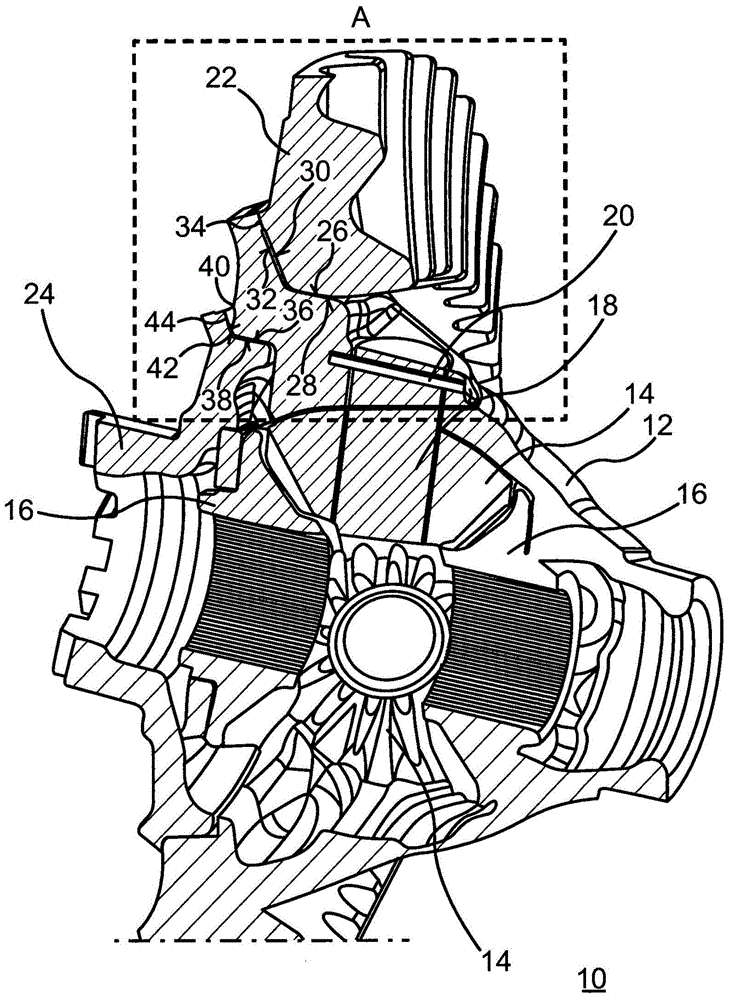
[0030] figure 1 and 2 A differential 10 for a motor vehicle is shown. The differential 10 comprises a first housing part 12 as a first transmission element, which is referred to as a differential housing and serves to accommodate adjusting gears 14 , 16 , which are here designed as bevel gears. The adjusting gear 16 can be connected in a rotationally fixed manner to a drive shaft of the motor vehicle so that the drive shaft of the motor vehicle and via said drive shaft the wheels are driven.

[0031] The adjusting gear 14 is designed, for example, as a warm forged component and is held on the first housing part 12 by means of corresponding screws 18 . Corresponding screws 18 are fastened to the first housing part 12 by means of pins 20 . This means that the screw 18 is immovable relative to the first housing part 12 , whereas the respective adjustment gear 14 is rotatable about it relative to the screw 18 .

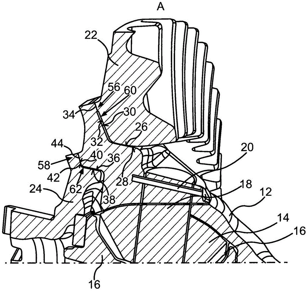
[0032] The differential 10 includes a crown gear 22 as a second ...


PUM


Abstract

The invention relates to a differential gear (10) for a motor vehicle, comprising at least one housing part (12) as a first gear part and a crown wheel (22) as a second gear part, these being interconnected, using a press-fit, by means of specific first connecting surfaces (26, 28) which run in the axial direction and also being interconnected, with the formation of a weld seam (34), by means of specific second connecting surfaces (30, 32) which run at an incline to the axial direction. One of the gear parts (12, 22) is formed from a steel and the other gear part (12) is formed from a cast iron material. The invention also relates to such a differential gear (10) in which the second connecting surfaces (30, 32) are directly attached to the first connecting surfaces (26, 28).

Description

technical field [0001] The invention relates to a differential for a motor vehicle according to the preambles of claims 1 and 5 . Background technique [0002] Such a differential for motor vehicles is known from document US Pat. No. 8,015,899 B2. The differential includes a housing member as a first transmission member and a crown gear as a second transmission member. The housing part and the crown gear are connected to each other by means of a press fit via respective first connection surfaces extending in the axial direction. Furthermore, the housing part and the crown gear are connected to one another by means of respective second connecting surfaces running obliquely to the axial direction which form weld seams running obliquely to the axial direction. This known differential has high manufacturing costs. Contents of the invention [0003] It is therefore the object of the present invention to improve a differential of the type mentioned at the outset in such a way...

Claims


Application Information

Patent Timeline
Patent Type & Authority Applications(China)
IPC IPC(8): F16H48/40
CPCF16H2048/385F16H48/38F16H2048/382F16H48/08F16H48/40F16H55/06F16H2055/173
Inventor A·伯恩特A·邦廷C·埃尔斯纳C·克拉朱斯基H·科莱特L·托姆
Owner DAIMLER TRUCK AG
Why Eureka
Try Eureka