Punching device based on capacitance detection and photoelectric induction positioning

A photoelectric induction and punching device technology, which is applied in the field of sheet metal processing, can solve the problems of easy deformation of the sheet metal, low punching quality, and many burrs on the edge of the hole, and achieve the effects of improving processing quality, processing efficiency, and precise positioning

Inactive Publication Date: 2014-11-26
SUZHOU JINGYU AUTOMATION TECH
View PDF7 Cites 23 Cited by
  • Summary
  • Abstract
  • Description
  • Claims
  • Application Information

AI Technical Summary

Problems solved by technology

The disadvantages of the above-mentioned punching device or punching machine are: punching can only be performed according to the preset punching pressure, which cannot be adjusted in real time, the punching quality is low, the plate is easily deformed, there are many burrs on the edge of the hole, and there is no safety protection. device

Method used


Image

  • Punching device based on capacitance detection and photoelectric induction positioning
  • Punching device based on capacitance detection and photoelectric induction positioning

Examples


Embodiment Construction

[0011] The specific implementation manner of the present invention will be described below in conjunction with the accompanying drawings.

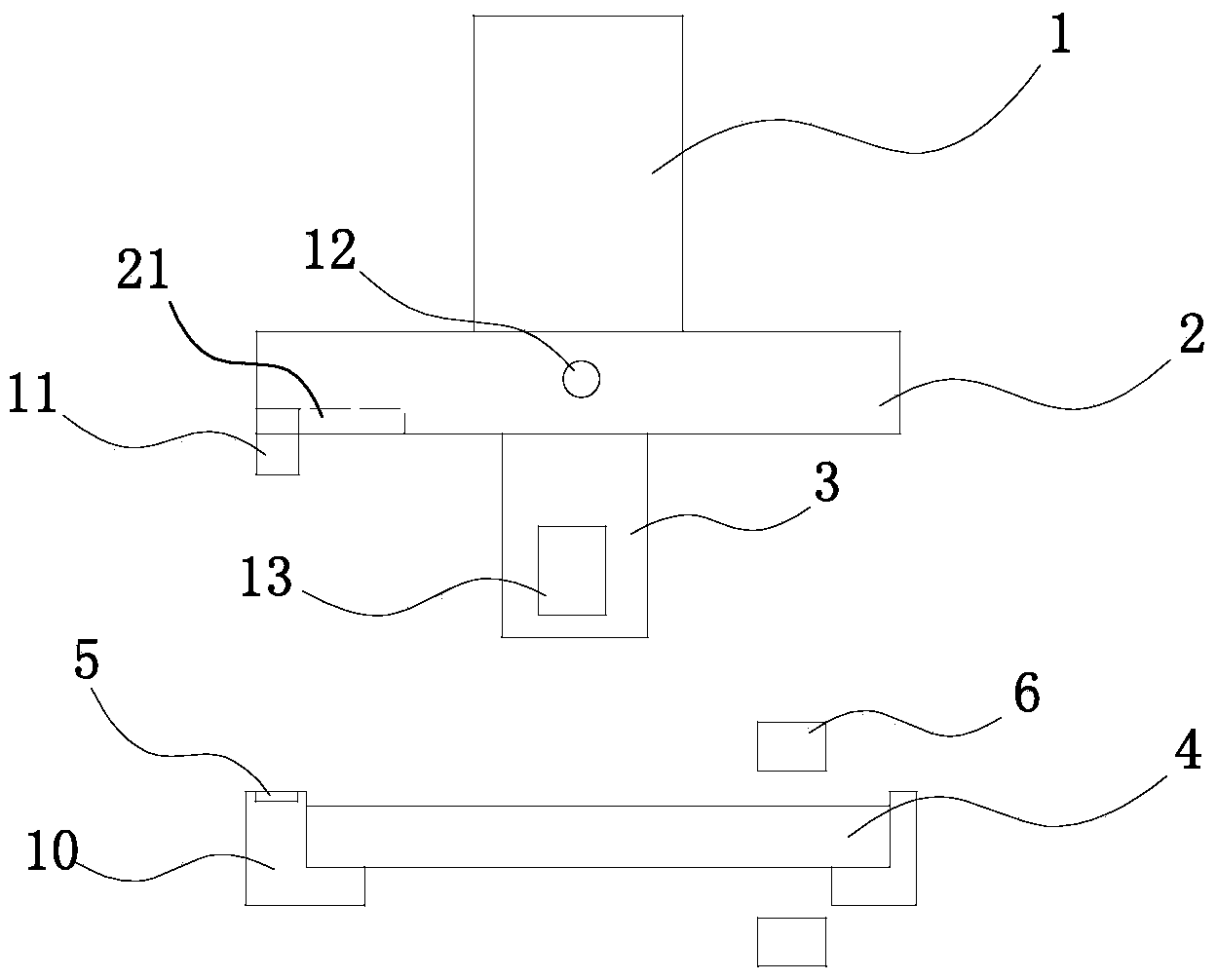
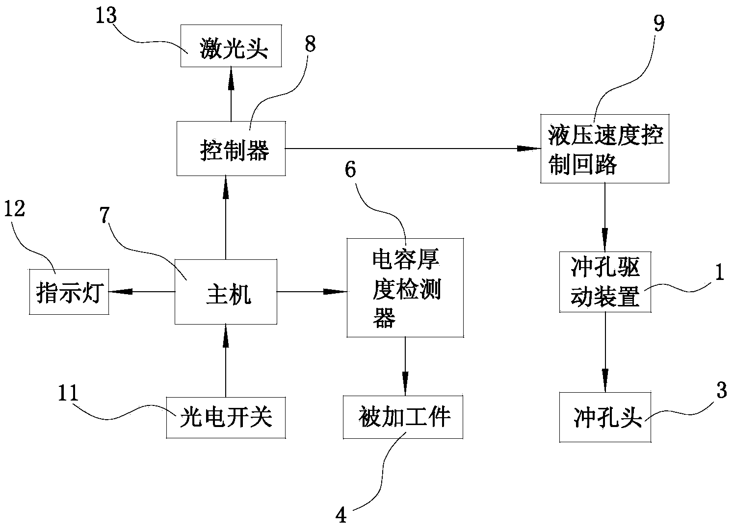
[0012] Such as figure 1 and figure 2 As shown, the punching device based on capacitance detection and photoelectric induction positioning in this embodiment includes a punching drive device 1, an upper template 2, a punching head 3, and a clamping device 10 located below the punching head 3. The workpiece 4 is installed in the device 10, and also includes a host 7, a controller 8, a hydraulic speed control circuit 9 and a capacitance thickness detector 6. The lower surface of the upper template 2 has a mounting groove 21, and the mounting groove 21 is installed with the host 7. The connected photoelectric switch 11, the front side of the upper template 2 is equipped with an indicator light 12 connected to the host 7; the clamping device 10 is equipped with a color mark 5 for photoelectric switch 11 detection; the output end of the host 7...


PUM


Abstract

The invention relates to a punching device based on capacitance detection and photoelectric induction positioning. The punching device based on capacitance detection and photoelectric induction positioning comprises a punching driving device, an upper die plate, a punching head and a clamping device located below the punching head, and a machined workpiece is mounted in the clamping device. The punching device comprises a mainframe, a controller, a hydraulic speed control loop, a capacitance thickness detector and a photoelectric switch. A color code for detecting the photoelectric switch is mounted on the clamping device, the output end of the mainframe is connected with the controller and the capacitance thickness detector, and a laser head is arranged in the punching head. According to the punching device, laser hole cutting and punching are combined, and machining efficiency is improved; the machined workpiece is accurately positioned through the photoelectric switch, and the punching device is accurate in positioning and convenient to operate. The thickness of the machined workpiece is detected, the punching speed and the laser energy are controlled through thickness, the defects of excessive deformation of plates due to the too high punching speed and burrs of the plates due to the too low punching speed are overcome, and machining quality is improved.

Description

technical field [0001] The invention relates to the technical field of sheet metal processing, in particular to a sheet metal punching machine. Background technique [0002] Existing punching devices or punching machines all include a frame, a bottom mold fixed on the frame, an upper template that moves up and down relative to the frame, and a punch corresponding to the bottom mold is fixed on the upper template. , the upper template is connected with the oil cylinder or cylinder that drives it to move up and down. Driven by the oil cylinder or air cylinder, the upper template drives the punch to move up and down relative to the bottom die, so as to punch out the required holes on the workpiece between the punch and the bottom die. The disadvantages of the above-mentioned punching device or punching machine are: punching can only be performed according to the preset punching pressure, which cannot be adjusted in real time, the punching quality is low, the plate is easily de...

Claims


Application Information

Patent Timeline
Patent Type & Authority Applications(China)
IPC IPC(8): B21D28/26B21D43/00B21C51/00
Inventor 不公告发明人
Owner SUZHOU JINGYU AUTOMATION TECH
Why Eureka
Try Eureka