
A New Vacuum Chamber Structure of Packaging Machine

A new type of packaging and vacuum chamber technology, applied in packaging, transportation packaging, transportation and packaging, etc., can solve the problems of unreachable and low efficiency, and achieve the effect of improving efficiency, improving efficiency, and avoiding easy food breakage

Inactive Publication Date: 2017-03-15
王君 +5
View PDF6 Cites 0 Cited by
  • Summary
  • Abstract
  • Description
  • Claims
  • Application Information

AI Technical Summary

Problems solved by technology

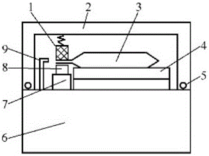
This kind of structure can only heat-seal the package 3 with the same quantity as the inflation nozzle 9 in each operation, and the efficiency is relatively low. On the other hand, products such as puffed food, bread, fish fillet, etc. cannot be eaten at one time after opening a package. If the remaining food is placed in the torn packaging bag, it cannot achieve the purpose of anti-compression, shatterproof, air-blocking, fresh-keeping, and keeping food dry.

Method used


Image

  • A New Vacuum Chamber Structure of Packaging Machine
  • A New Vacuum Chamber Structure of Packaging Machine
  • A New Vacuum Chamber Structure of Packaging Machine

Examples


Embodiment Construction

[0014] The technical scheme of the present invention will be described in further detail below in conjunction with the accompanying drawings and specific embodiments, so that those skilled in the art can better understand the present invention and implement it, but the examples given are not intended to limit the present invention.

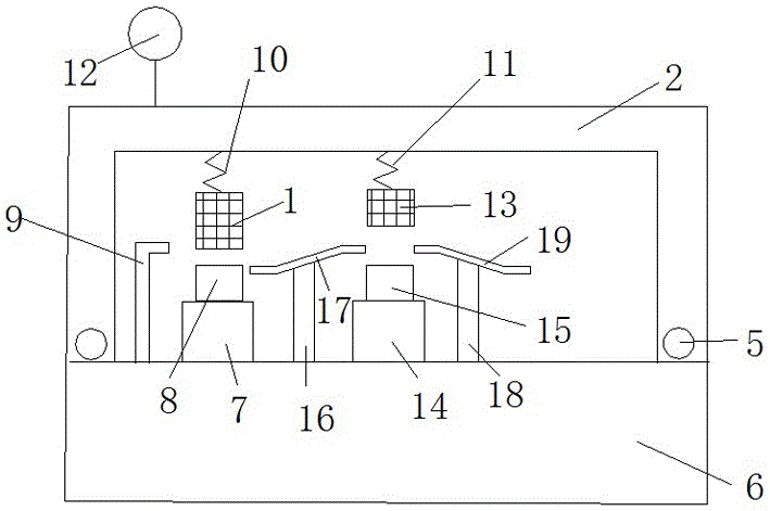
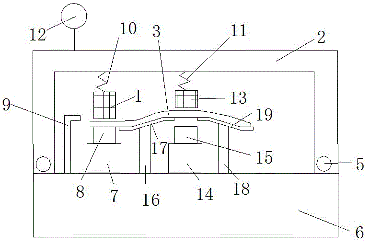
[0015] Such as figure 2 As shown, the vacuum chamber structure of a new type of packaging machine includes a box body 6 at the bottom and a vacuum chamber cover 2 at the top, and a sealing gasket 5 is arranged between the vacuum chamber cover 2 and the box body 6 . The inside of the vacuum chamber cover 2 is connected to a rubber backing plate 1 through a first spring 10, and a central rubber backing plate 13 is connected through a second spring 11, wherein both the rubber backing plate 1 and the central rubber backing plate 13 are heat-resistant rubber backing plates . It should be noted that, in order to facilitate the distinction figure 2 T...


PUM


Abstract

The invention discloses a vacuum chamber structure of a novel packaging machine. The vacuum chamber structure comprises a box body at the bottom and a vacuum chamber cover at the top. The inner portion of the vacuum chamber cover is connected with a rubber cushion plate through a first spring. The box body is provided with a pressurizing device corresponding to the rubber cushion plate. A heat-seal rod is arranged on the pressurizing device. An air inflation pipe opening is formed in the box body. The vacuum chamber structure is characterized in that the inner portion of the vacuum chamber cover is connected with a center rubber cushion plate through a second spring, a center pressurizing device corresponding to the center rubber cushion plate is arranged on the box body, a center heat-seal rod is arranged on the center pressurizing device, a first supporting column is arranged between the pressurizing device and the center pressurizing device, a first supporting plate is arranged on the first supporting column, a second supporting column is arranged on the other side of the center pressurizing device, and a second supporting plate is arranged on the second supporting column. Heat-seal efficiency is improved.

Description

technical field [0001] The invention relates to a novel vacuum chamber structure of a packaging machine. Background technique [0002] To put it simply, a packaging machine is a machine that packs products, which plays the role of protection and beauty. Among them, the vacuum inflatable packaging machine is to put food into the packaging bag, extract the air in the packaging bag to reach the predetermined vacuum degree, and then fill it with nitrogen or other mixed gases, and finally complete the sealing process. Such as puffed food, bread, fish fillets and other products, this packaging method is often used to fill the product with gas, which has the advantages of compression resistance, shatterproof, gas resistance, freshness preservation, and food dryness. [0003] The vacuuming, inflation and sealing of the vacuum inflatable packaging machine are all completed in the vacuum chamber. The traditional vacuum chamber structure is as follows: figure 1 As shown, the heat-sea...

Claims


Application Information

Patent Timeline
Patent Type & Authority Patents(China)
IPC IPC(8): B65B31/02B65B51/10
Inventor 汪雨
Owner 王君
Learn More