
Band-gap reference source adjusting circuit

A technology of reference source circuit and adjustment circuit, which is applied in the direction of adjusting electrical variables, control/regulation systems, instruments, etc., and can solve the problems of consuming chip area and testing time

Active Publication Date: 2014-11-26
CHINA RESOURCES MICROELECTRONICS (CHONGQING) CO LTD
View PDF7 Cites 20 Cited by
  • Summary
  • Abstract
  • Description
  • Claims
  • Application Information

AI Technical Summary

Problems solved by technology

It can be found that in the prior art, if trying to obtain a reference voltage that is safe and meets the expected standard, it often consumes a lot of chip area and test time

Method used


Image

  • Band-gap reference source adjusting circuit
  • Band-gap reference source adjusting circuit
  • Band-gap reference source adjusting circuit

Examples


Embodiment Construction

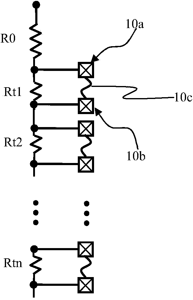
[0023] exist figure 1, shows a group of trimming resistors Rt1, Rt2...Rtn connected in series, they are connected in series with a fixed resistor R0, and each trimming resistor Rtn (n is a natural number other than 0) is connected in parallel with a fuse 10c, when the resistor R0 cannot meet the resistance requirement, the fuse 10c connected in parallel with the trimming resistor Rtn can be blown. The trimming resistor Rtn was originally short-circuited by the fuse 10c and did not show resistance characteristics. Once the fuse 10c no longer exists, the trimming resistor Rtn is introduced into the circuit and becomes effective. The resistor R0 plus the resistance of several trimming resistors Rtn can provide the required resistance. On the chip with built-in fuses, the two ends of each fuse 10c are respectively electrically connected to two soldering pads 10a, 10b provided on the front side of the chip, and the soldering pads 10a, 10b are used to carry the applicable As for t...


PUM


Abstract

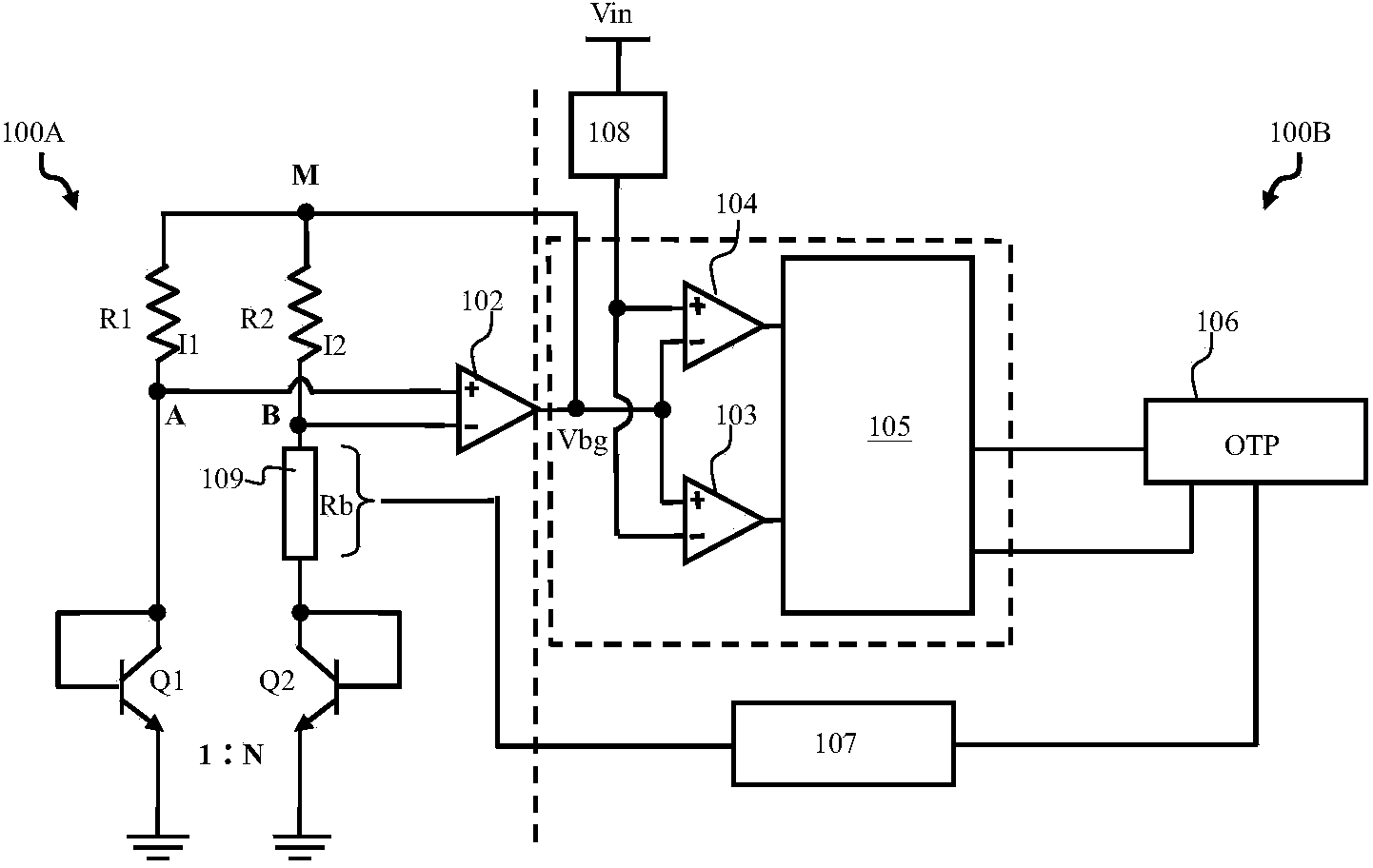
The invention mainly relates to a band-gap reference voltage source, and more exactly relates to a band-gap reference source adjusting circuit with a band-gap reference source and a self alignment fine adjustment circuit integrated on the same wafer. The self alignment fine adjustment circuit can conduct correction and fine adjustment on a reference voltage value when the band-gap reference voltage value and a target voltage value deviate. A single finished product testing phase calibration mode is used for replacing the multi-calibration means that finished product testing phase calibration is implemented after wafer level testing in the prior art, a fuse wire calibration mode is replaced, so that the integration level is high, and the wafer with a smaller area can be provided.

Description

technical field [0001] The present invention mainly relates to a bandgap reference voltage source, more precisely, it is designed to integrate a bandgap reference source and a self-alignment fine-tuning circuit on the same chip, and the self-alignment fine-tuning circuit can be used between the bandgap reference voltage value and the When the target voltage value deviates, the reference voltage value is corrected and fine-tuned. Background technique [0002] For calibrating the bandgap reference source voltage, a reference reference voltage is often generated inside the IC to provide a comparison reference for the entire circuit system voltage. The bandgap voltage reference circuit is well known in technology, and usually needs to be implemented in the occasion of providing a temperature-independent regulated power supply in a wide operating temperature range. The emitter-base voltage of the bipolar transistor (that is, understood as CTAT voltage or The positive temperature...

Claims


Application Information

Patent Timeline
Patent Type & Authority Applications(China)
IPC IPC(8): G05F1/56
Inventor 吴建兴
Owner CHINA RESOURCES MICROELECTRONICS (CHONGQING) CO LTD
Learn More