A mmc with zero DC voltage fault ride-through capability and its design method
A technology of DC voltage and fault ride-through, which is applied in the direction of electrical components, power transmission AC network, output power conversion device, etc. It can solve the problems of decreased operating efficiency, increased on-state loss, inability to inject reactive power into the grid to support the grid voltage, etc. problem, to achieve the effect of low cost and high operating efficiency
- Summary
- Abstract
- Description
- Claims
- Application Information
AI Technical Summary
Problems solved by technology
Method used
Image

Examples
Embodiment 1
[0035] The design method of MMC includes the following steps:
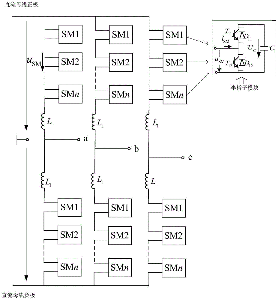
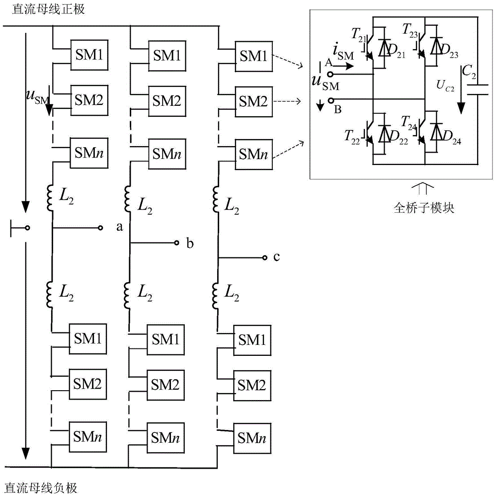
[0036] (1) In order to reduce the design cost of the MMC and improve its operating efficiency, the half-bridge sub-module is selected as the first sub-module of the MMC; in order to enable the MMC to have zero DC voltage ride-through capability, a full-bridge sub-module that can output negative levels in the non-blocking state is selected. The bridge sub-module is the second sub-module of the MMC. The topology of the formed MMC is as Figure 5 shown.
[0037](2) Determine the zero DC voltage fault ride-through scheme. Among them, the ride-through scheme follows the following principles: all half-bridge sub-modules are bypassed, the impedance of the AC current in the bridge arms is ignored, the total output voltage of the full-bridge sub-modules of the same phase upper and lower The total output voltage of the bridge sub-module is the instantaneous value of the phase voltage of the current AC side, and its equiv...
Embodiment 2
[0061] The design method of MMC includes the following steps:
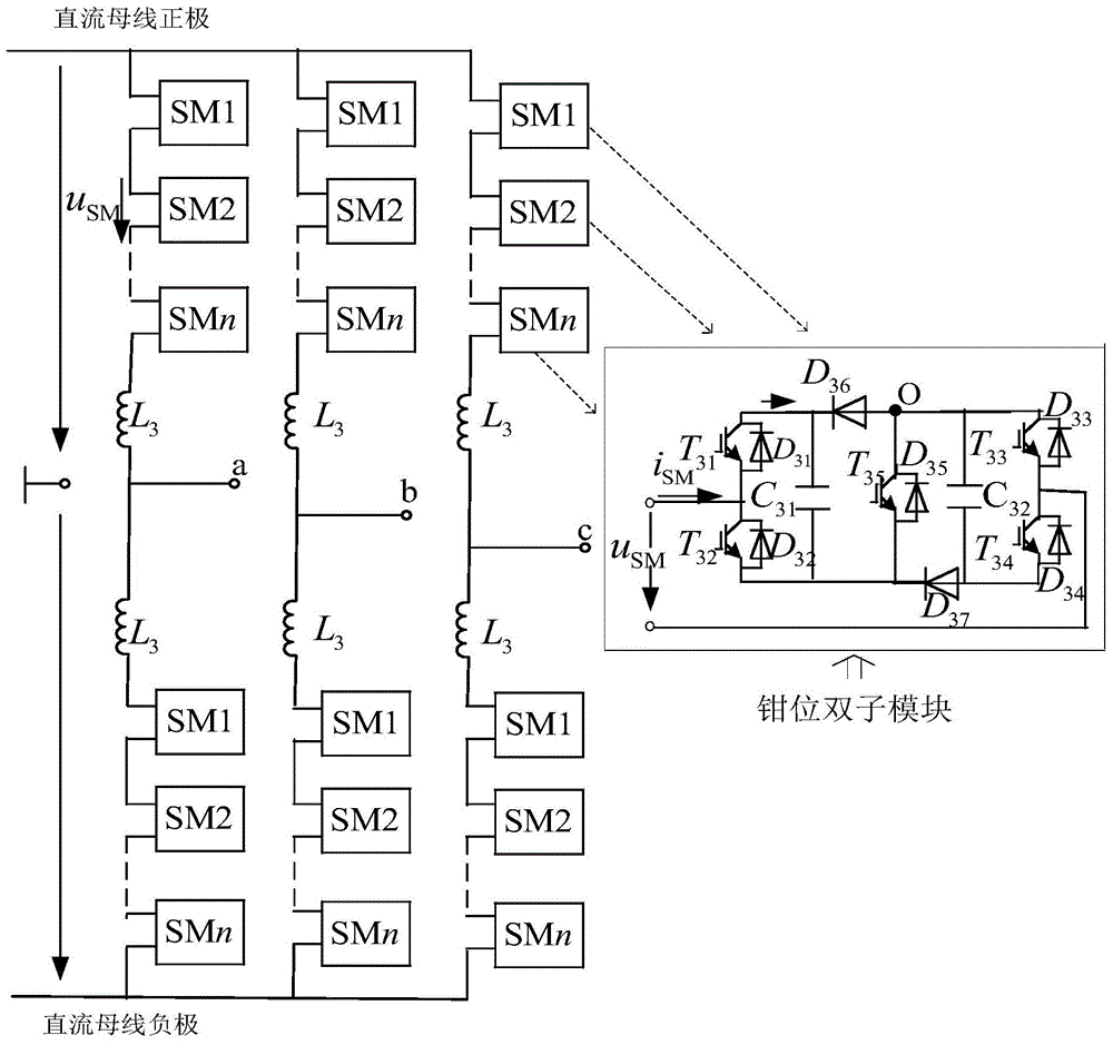
[0062] (1) In order to reduce the design cost of the MMC and improve its operating efficiency, the half-bridge sub-module is selected as the first sub-module of the MMC; in order to enable the MMC to have zero DC voltage ride-through capability, a crossover that can output negative levels in the non-blocking state is selected Connect the dual half-bridge sub-module as the second sub-module of the MMC. The topology of the formed MMC is as Figure 7 shown.
[0063] (2) Determine the zero DC voltage fault ride-through scheme. Among them, the ride-through scheme follows the following principles: all half-bridge sub-modules are bypassed, the impedance of the AC current in the bridge arms is ignored, the cross-connected double half-bridge sub-modules of the same phase upper and lower The total output voltage of the bridge arm cross-connected double-half-bridge sub-module is the instantaneous value of the current phas...
PUM
 Abstract
Description
Claims
Application Information
PatSnap Eureka turns technology decisions into work you can execute. Powered by our Innovation Knowledge Graph, it runs expert workflows across engineering, life sciences, materials and intellectual property. Get your review-ready output in minutes.


