

scr treatment of engine exhaust using temperature control
一种排气处理、内燃发动机的技术,应用在排气处理、排气处理装置的电控、排气处理装置的诊断装置等方向
- Summary
- Abstract
- Description
- Claims
- Application Information
AI Technical Summary
Problems solved by technology
Method used
Image

Examples
Embodiment Construction
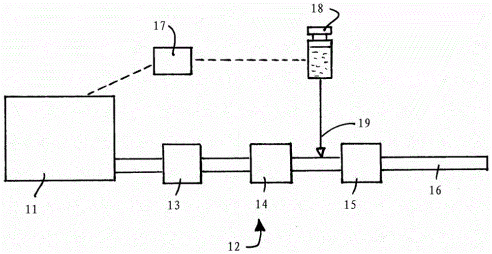
[0022] refer to figure 1 A diesel internal combustion engine 11 has an exhaust tract or system 12 comprising a diesel oxidation catalyst (DOC) 13 , a diesel particulate filter (DPF) 14 and a catalyst 15 for selective catalytic reduction. The exhaust duct ends with an open tailpipe 16 .
[0023] An engine management system (EMS) 17 electronically controls the operation of the engine, particularly the fueling of the engine, based on programmed information, real-time monitoring, and driver demand. Such engine management systems are well known and need not be further described here.
[0024] A container 18 of liquid urea is provided for periodic dosing of the exhaust tract as indicated by arrow 19 under the control of the EMS 17; as described above, the urea mixes with the exhaust gas to produce ammonia, which supplements the SCR catalyzed by the ammonia device. The mixing takes place in the region of the exhaust tract where urea is supplied, referred to herein as the make-up r...
PUM
 Abstract
Description
Claims
Application Information