Motor vehicle door lock

A car door lock and locking technology, used in vehicle locks, electric car locks, electric locks, etc., can solve problems such as affecting comfort, and achieve the effect of improving comfort, satisfying door lock quality, and compact structure

Active Publication Date: 2014-11-26
HUF HULSBECK & FURST GMBH & CO KG
View PDF5 Cites 14 Cited by
  • Summary
  • Abstract
  • Description
  • Claims
  • Application Information

AI Technical Summary

Problems solved by technology

When the detent pin disengages the rotary latch, the pressure exerted by the seal is released suddenly in the direction of said relief impact, causing an audible opening noise that affects comfort

Method used


Image

  • Motor vehicle door lock
  • Motor vehicle door lock
  • Motor vehicle door lock

Examples


Embodiment Construction

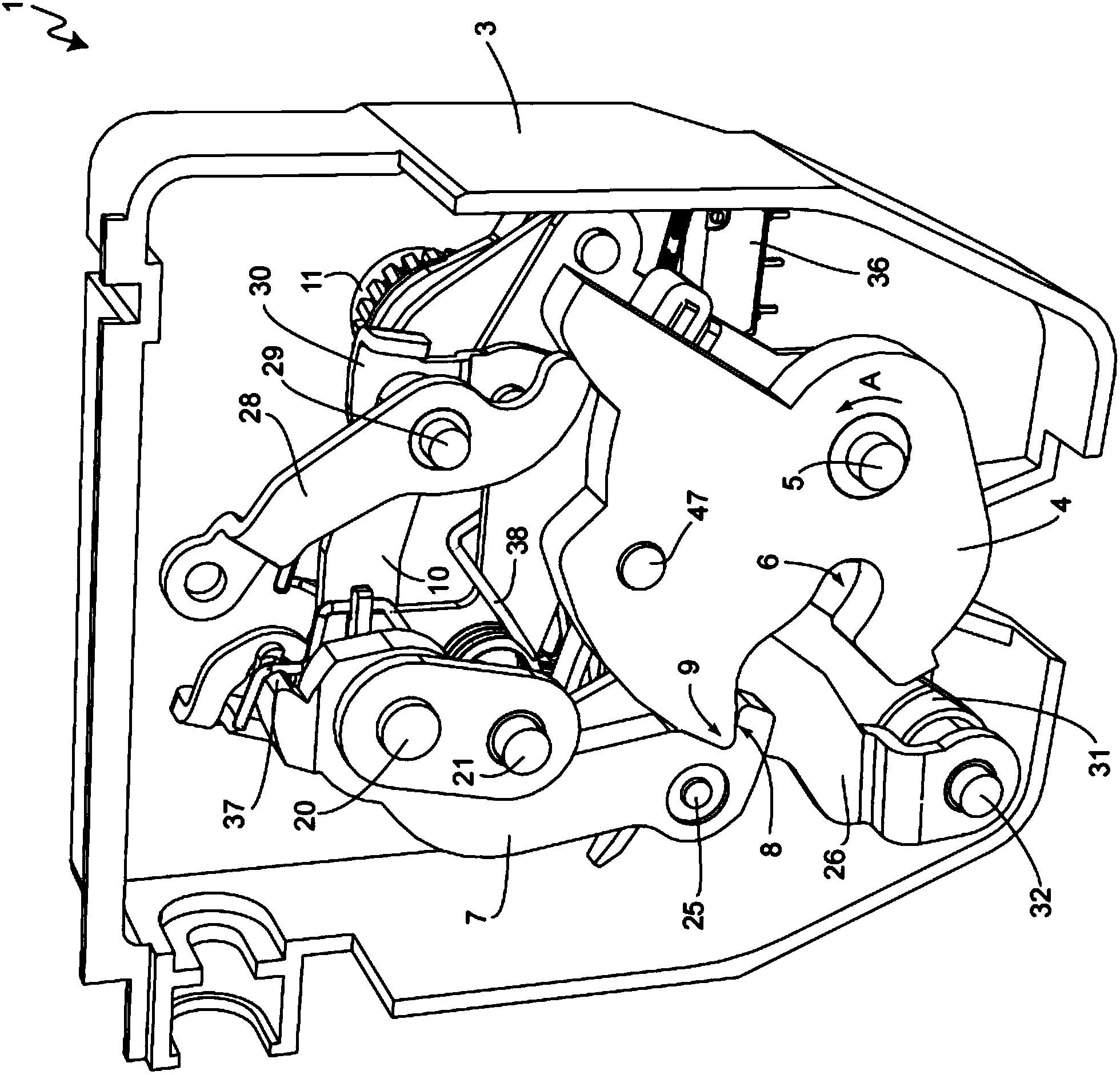
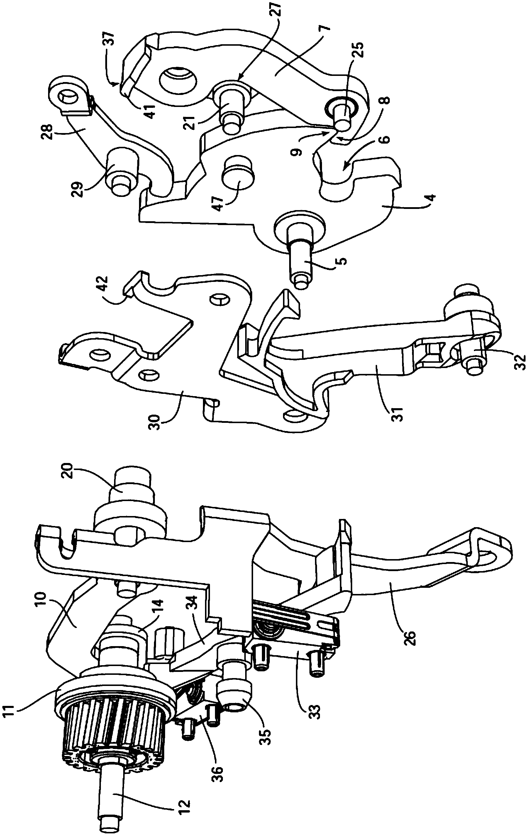
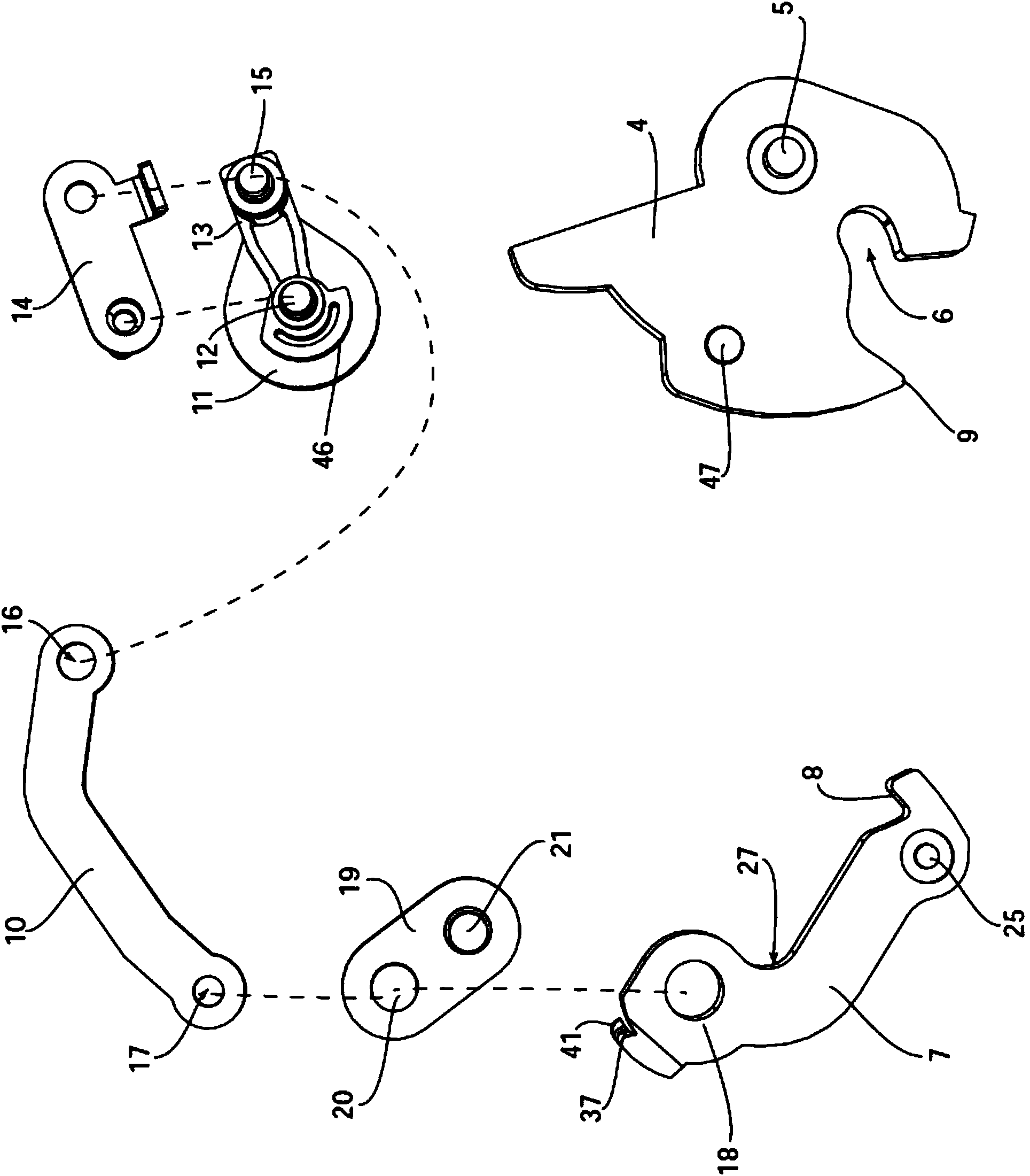
[0049] figure 1 Shown is a perspective view of a vehicle door lock 1 of the present invention, primarily a trunk lid lock assembly. The car door lock 1 is installed in the trunk lid of the car, and can be stuck only in the Figure 4 and 13 Locking part 2 shown in . The locking part 2 can be used as a locking bolt or a locking column and fixed on the vehicle frame. The vehicle door lock 1 comprises a housing part 3 in which the other components of the vehicle lock 1 are accommodated. In order to better see the inner structure housing part 3 is only in figure 1 displayed in . refer to Figures 1 to 5 , The car door lock 1 also has a rotary latch 4, which is fixed on the housing part 3 and can rotate around a fixed rotating shaft 5 and has a rotary latch groove 6, and the locking part 2 is fixed in the groove. Rotary latch 4 exerts prestress or spring force through a spring part not shown in the figure, so that said latch is Figures 1 to 4 Turn counterclockwise in the di...


PUM


Abstract

The invention relates to a motor vehicle door lock (1), comprising a rotary latch (4) that in a locking position encompasses a locking element (2) and that is pre-tensioned in the direction of an open position releasing the locking element (2), a pawl (7) that, in an engagement position with the rotary latch (4), is engaged in such a manner that the rotary latch (4) is inhibited from moving in the direction of the open position, and a drive element (11), by means of which a coupling section (18) of the pawl is coupled in terms of movement and which moves the pawl (7) between an engagement position and a release position in which the pawl (7) is not engaged with the rotary latch (4), so that the rotary latch (4) can move in the direction of the open position. The invention aims at creating a solution by means of which a reliably working motor vehicle door lock having a compact design is provided both in a simple manner in terms of design and cost-effectively, said motor vehicle door lock being able to make do with a motor operating on a low energy level. This is achieved in that force is applied to the pawl (7) only in the engagement position thereof and the force application holds the pawl (7) in engagement with the rotary latch (4).

Description

technical field [0001] The invention relates to a car door lock, which has a locking part which is closed in the locking position, a rotating latch which is prestressed in the direction of releasing the locking part, and a rotating latch which is in the locking position and rotates The positioning pin locked together by the latch, the rotating latch cannot move in the opening direction, a connecting part of the positioning pin is connected to the driving member for movement, the positioning pin moves between the locked position and the open position, and the position is positioned at this position The pin is disengaged from the rotary latch, which can be moved to the opening direction, Background technique [0002] A vehicle door lock of the type described above has already been described in DE 10 2007 024 672 A1 and is used in the trunk lid of a vehicle. The vehicle door lock comprises a door lock device mounted on the trunk lid and in most cases equipped with a rotary lat...

Claims


Application Information

Patent Timeline
Patent Type & Authority Applications(China)
IPC IPC(8): E05B81/06E05B47/00E05B85/20
CPCE05B81/20E05B81/68E05B15/04E05B77/06E05B2047/0065E05B81/14E05B77/36E05B81/06E05B83/18E05B85/26Y10T292/1043E05B85/20
Inventor 阿图尔·托尔卡乌多·奥泽切斯蒂芬·维特坎普
Owner HUF HULSBECK & FURST GMBH & CO KG
Why Eureka
Try Eureka