Wheeled mobile robot platform
A mobile robot and platform technology, applied in the field of robotics, can solve problems such as difficult to ensure the level of the body platform, complex structure, low efficiency, etc., and achieve the effects of overcoming poor terrain adaptability, low energy consumption, and convenient control
- Summary
- Abstract
- Description
- Claims
- Application Information
AI Technical Summary
Problems solved by technology
Method used
Image

Examples
Embodiment 1
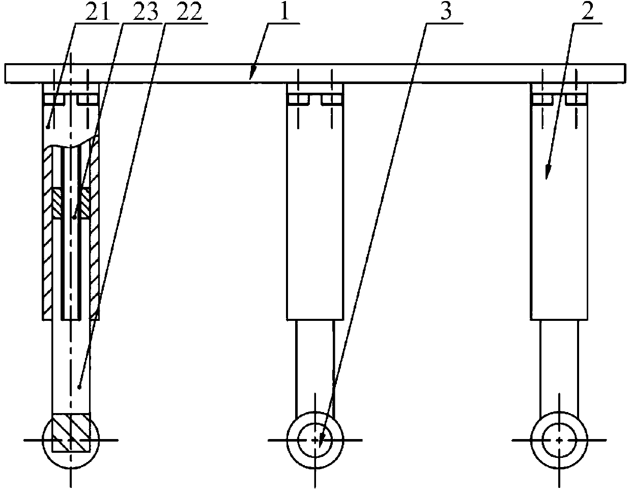
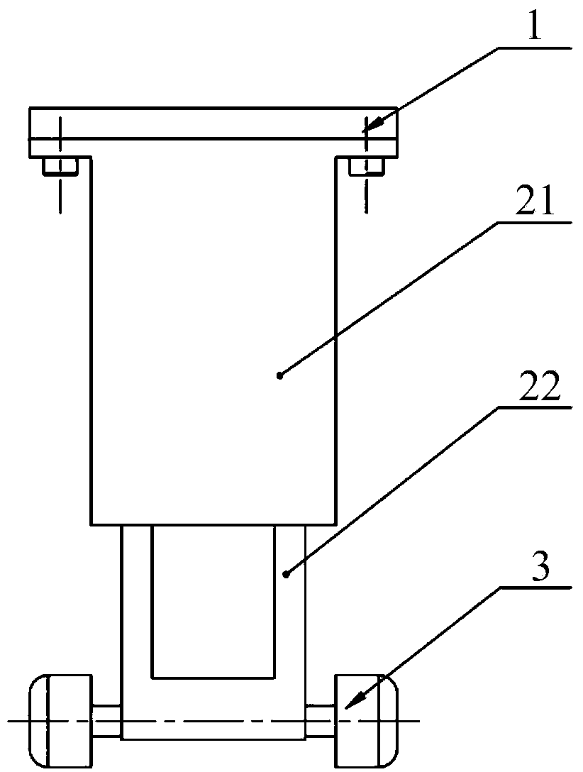
[0021] In this embodiment, the number of support frames 2 is three, and the linear motion unit 23 adopts a ball screw type linear motion unit. The support frame base 21 is a hollow cylinder with a cavity inside, and the linear motion unit 23 is installed on the support frame base. In the cavity of the seat 21, the mobile unit 22 is a sliding part matched with the support frame base 21, the support frame base 21 and the mobile unit 22 constitute a moving pair, the support frame base 21, the mobile unit 22 and the linear motion unit 23 The axes of the three are parallel and perpendicular to the plane of the body 1 . The mobile pair is driven by the linear motion unit 23, and the lower end of each mobile unit 22 is symmetrically arranged on two wheels 3, and the wheels 3 are motor-driven wheels.
Embodiment 2
[0023] In the present embodiment, the number of support frames 2 is five, and the linear motion unit 23 adopts a belt-driven linear motion unit. The support frame base 21 is a hollow square prism with a cavity inside. In the cavity of the seat 21, the mobile unit 22 is a sliding part matched with the support frame base 21, the support frame base 21 and the mobile unit 22 constitute a moving pair, the support frame base 21, the mobile unit 22 and the linear motion unit 23 The axes of the three are parallel and perpendicular to the plane of the body 1 . The mobile pair is driven by the linear motion unit 23, and the lower end of each mobile unit 22 is symmetrically arranged on two wheels 3. The wheel 3 is an active movement mechanism, and driven by its built-in motor, it can drag the platform to move, and then realize the forward, backward and differential turning of the platform.
Embodiment 3
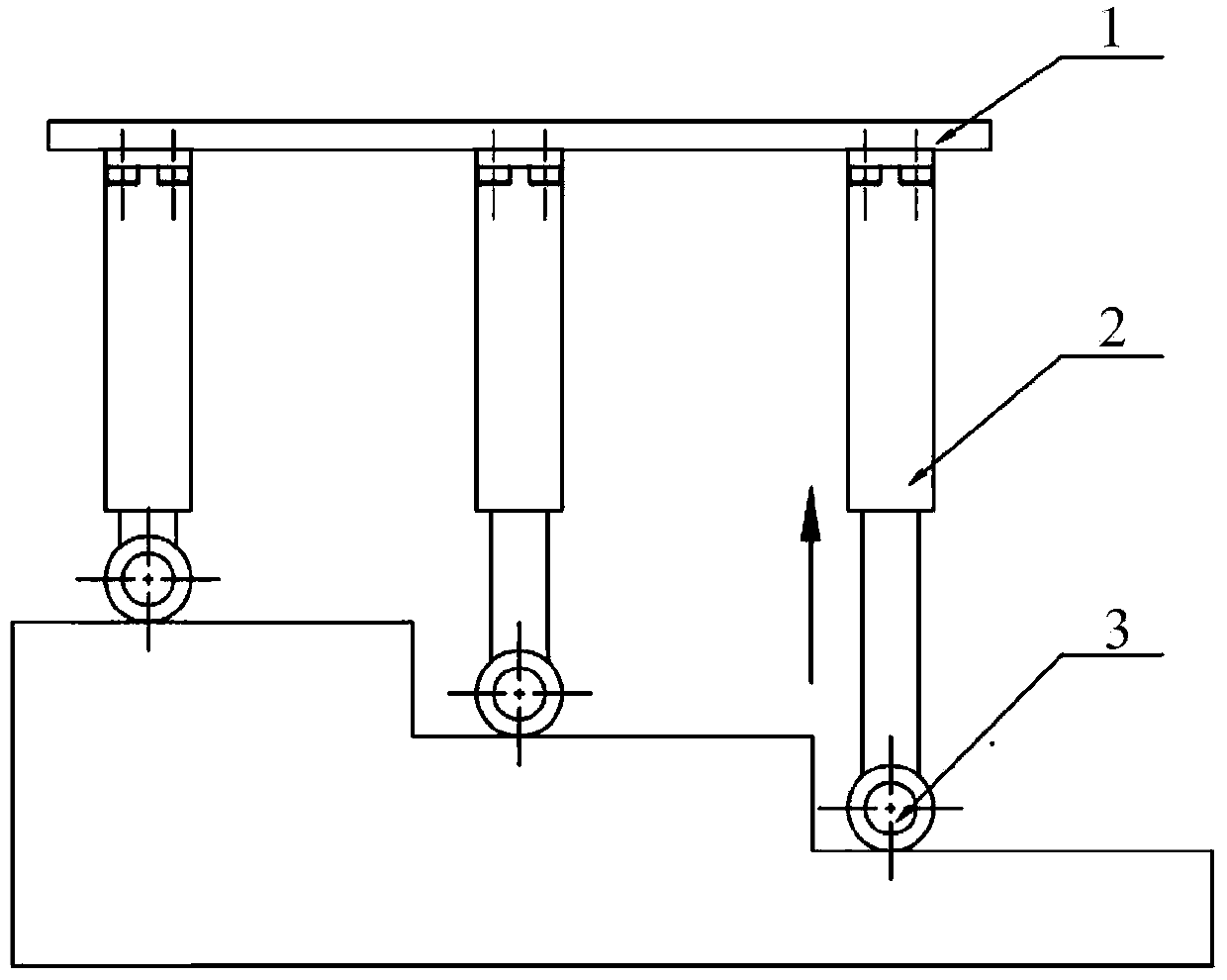
[0025] The quantity of support frame 2 in the present embodiment is 8, and linear motion unit 23 adopts pneumatic type linear motion unit, and support frame base 21 is a hollow prism, and the inside is a cavity, and linear motion unit 23 is installed on support frame base 21 In the cavity, the mobile unit 22 is a sliding part matched with the support frame base 21, the support frame base 21 and the mobile unit 22 constitute a moving pair, the support frame base 21, the mobile unit 22 and the linear motion unit 23 three The axes are parallel to and perpendicular to the plane of the body 1. The mobile pair is driven by the linear motion unit 23, and the lower end of each mobile unit 22 is symmetrically arranged on two wheels 3. The wheel 3 has the initiative of mechanical movement, driven by its built-in motor, it can drag the platform to move, and then realize the forward, backward and differential speed turning of the platform. When the platform walks on uneven terrain, under...
PUM
 Abstract
Description
Claims
Application Information