Built-in marine heat pipe mounting structure
An installation structure, built-in technology, applied in the direction of hull ventilation/heating/cooling, ship components, ship construction, etc., can solve problems such as high cost, inability to meet heat pipe heat exchangers, and unsatisfactory use of heat exchangers, etc. Achieve the effect of low manufacturing cost, space saving, and saving circulating cooling water resources
- Summary
- Abstract
- Description
- Claims
- Application Information
AI Technical Summary
Problems solved by technology
Method used
Image

Examples
Embodiment 1
[0025] A built-in marine heat pipe installation structure:
[0026] It includes a marine heat pipe shell and a marine heat pipe body built in the marine heat pipe shell. The marine heat pipe shell is composed of a shipboard cabin and a partition that is sealed and connected with the shipboard cabin; The externally connected heat pipe is cooled with a water inlet and a water outlet.
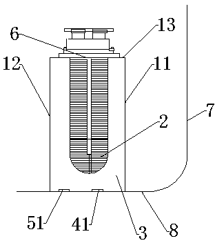
[0027] The present invention comprises marine heat pipe 2, clapboard a11, clapboard b12, clapboard c13 and ship's side cabin body 3, clapboard a11, clapboard b12, clapboard c13 and ship's side cabin body form airtight space 3; Confined space 3 is respectively provided with The water inlet 41 and the water outlet 51 are provided with a marine heat pipe 2 placement opening 6 on the partition c13 where the upper part of the confined space 3 is located. The distance between the marine heat pipe 2 placement opening 6 and the vertical side of the ship's side cabin is 1 / 3. Set in the closed space 3 thro...
Embodiment 2
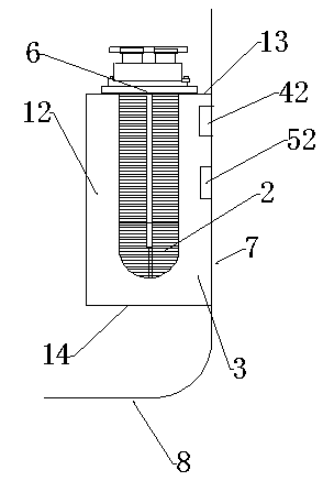
[0031] The built-in marine heat pipe installation structure of the present invention includes a marine heat pipe, a partition b12, a partition c13, a partition d14, and a ship's side cabin, and the partition b12, the partition c13, the partition d14 and the ship's side cabin form a closed space 3; the closed space 3 are respectively provided with a water inlet 42 and a water outlet 52, and the partition c13 where the upper part of the confined space 3 is located is provided with a marine heat pipe 2 placement opening 6, and the distance between the marine heat pipe 2 placement opening 6 and the vertical side of the ship's side cabin is 1 / 2. The marine heat pipe is installed in the confined space through the opening 6;
[0032] Specifically, the above-mentioned shipboard cabin body is the shipboard side 7, and the shipboard side is provided with upper and lower two ports, the upper port is the water inlet 42, and the lower port is the water outlet 52; the aperture size ratio of...
Embodiment 3
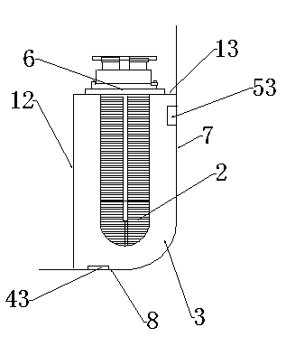
[0035] The built-in marine heat pipe installation structure of the present invention includes a marine heat pipe 2, a partition b12, a partition c13 and a ship's side cabin, and the partition b12, the partition c13 and the ship's side cabin form a closed space 3; the closed spaces 3 are respectively provided with water inlets 43 and the water outlet 53, the partition c13 where the upper part of the confined space 3 is located is provided with a marine heat pipe 2 placement opening 6, the distance between the marine heat pipe 2 placement opening 6 and the vertical side of the ship's side cabin is 1 / 2, and the marine heat pipe 2 passes through the opening placed in a confined space 3;
[0036] Specifically, the above-mentioned shipboard cabin body is a radian surface formed by the shipboard side 7 and the shipboard bottom surface 8, a closed space formed by the shipboard heat pipe 2, the partition b12, the partition c13, and the radian surface formed by the shipside side 7 and th...
PUM
 Abstract
Description
Claims
Application Information
 - R&D
- Intellectual Property
- Life Sciences
- Materials
- Tech Scout
- Unparalleled Data Quality
- Higher Quality Content
- 60% Fewer Hallucinations
Browse by: Latest US Patents, China's latest patents, Technical Efficacy Thesaurus, Application Domain, Technology Topic, Popular Technical Reports.
© 2025 PatSnap. All rights reserved.Legal|Privacy policy|Modern Slavery Act Transparency Statement|Sitemap|About US| Contact US: help@patsnap.com