Traction system for traction type elevator

A traction system and traction-type technology, which is applied in the field of traction systems, achieves the effects of convenient implementation, meeting installation requirements, and low cost

Inactive Publication Date: 2014-12-03
BOSTON ELEVATOR SUZHOU
View PDF10 Cites 1 Cited by
  • Summary
  • Abstract
  • Description
  • Claims
  • Application Information

AI Technical Summary

Problems solved by technology

[0003]However, in the installation of elevators, due to the different frame structures provided by different manufacturers, once there is a temporary replacement of the manufacturer, the original reserved traction rope The hole passed through will not be able to meet the manufacturer's installation after replacement, which will bring great inconvenience to the actual operation
[0004]At the same time, due to the different sizes of the machine rooms that customers need to install, the center distance between the guide wheel and the traction wheel of the traction machine is constant, which leads to The center distance between the car top wheel and the counterweight wheel cannot be adjusted. Once the center distance between the car top wheel and the counterweight wheel cannot meet the installation requirements, the elevator equipment will not be able to be installed
[0005]In addition, due to the need for one-to-one correspondence with the traction system when installing the elevator equipment mentioned above, the manufacturer cannot realize mass production and modularization in the order-based elevator industry. Quantification, and standardized production

Method used


Image

  • Traction system for traction type elevator
  • Traction system for traction type elevator
  • Traction system for traction type elevator

Examples


Embodiment Construction

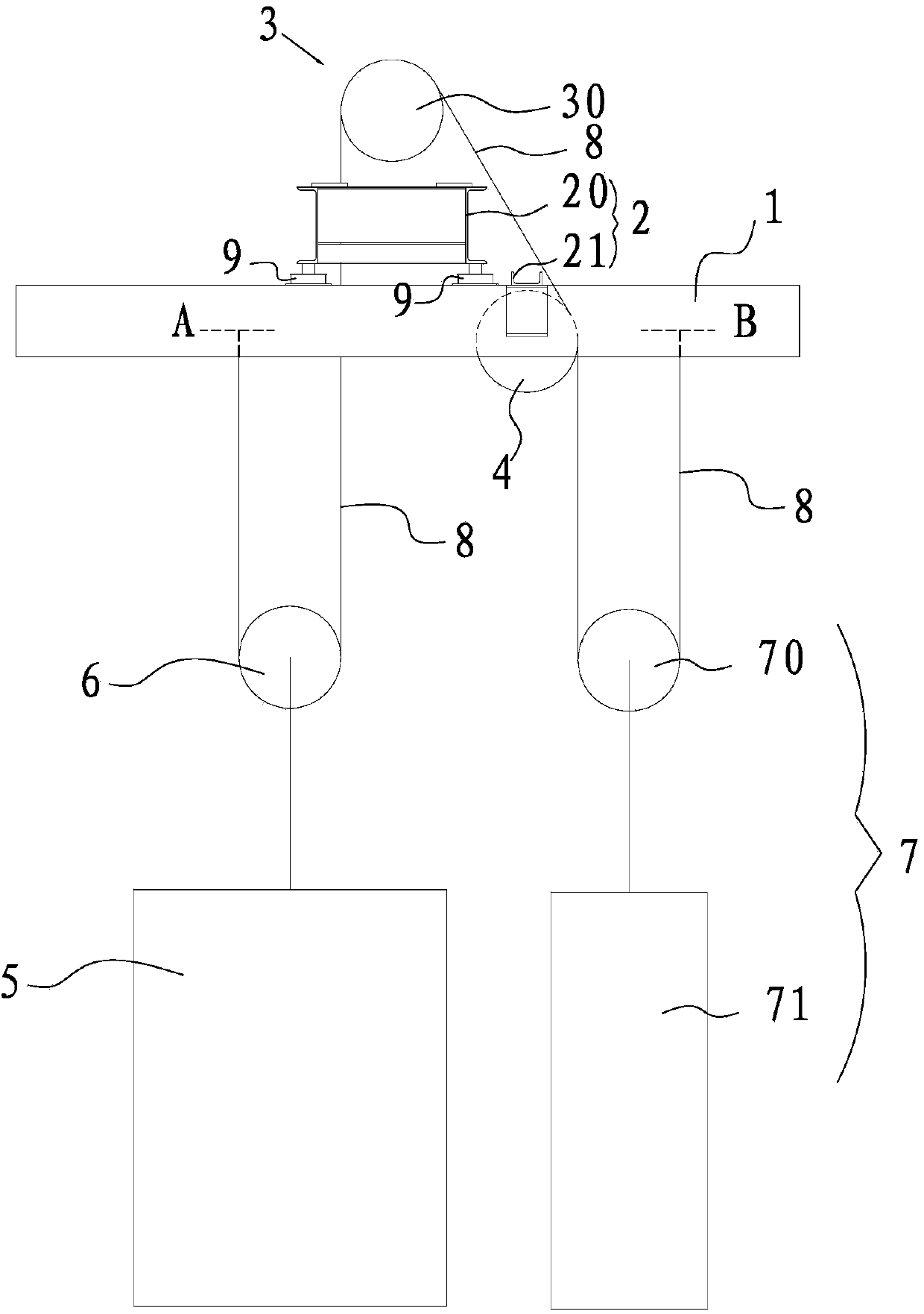
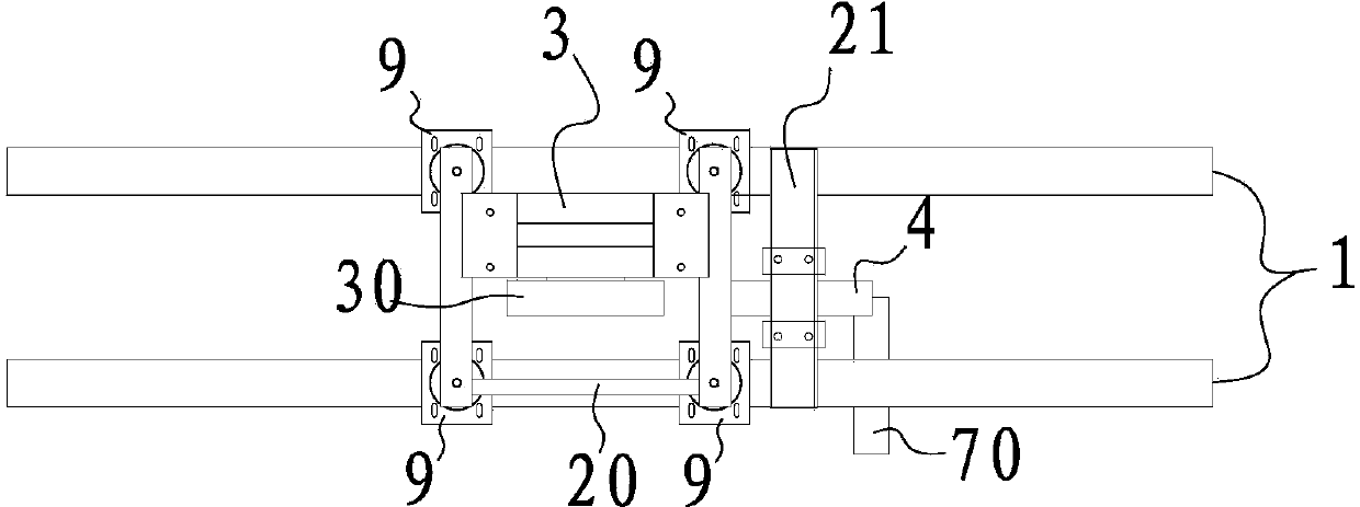
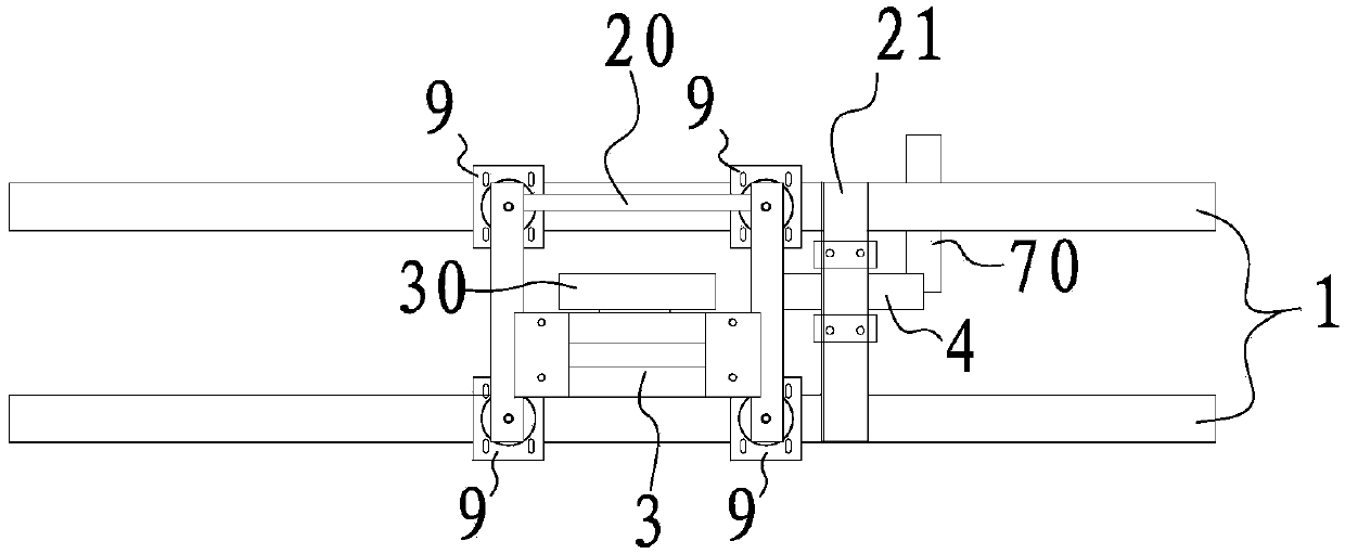
[0019] Such as Figure 1 to Figure 3 As shown, the traction system of the traction elevator in this embodiment includes a frame 2 erected on the frame 1, a traction machine 3 and guide wheels 4 arranged on the frame 2, and a car 5, the car top wheel 6 at the top is used for the counterweight mechanism 7 of the counterweight car 5 and is used to connect the traction sheave 30 of the traction machine 3, the guide wheel 4 and the counterweight wheel 70 of the counterweight mechanism 7 and The two ends are respectively fixed on the traction rope 8 on the machine girder 1 .

[0020] In this example, the above-mentioned frame 2 adopts a split type, and specifically includes a traction frame 20 for installing the traction machine 3, and a guide wheel frame 21 that can move horizontally and is arranged on the horizontal beam 1. The traction machine The frame 20 is arranged symmetrically along the center line parallel to the extension direction of the machine girder 1, and the gui...


PUM


Abstract

The invention discloses a traction system for a traction type elevator. The traction system comprises a rack, a traction machine and a guide pulley, a crosshead sheave arranged at the top of a lift car, a counterweight mechanism used for balancing the weight of the lift car, and a traction rope, wherein the rack comprises a traction rack used for mounting the traction machine, and a guide pulley support which can move horizontally and is arranged on a machine bearing beam; the traction rack is symmetric about the central line, in parallel to the extension direction of the machine bearing beam, of the traction rack; the guide pulley support can be erected on the machine bearing beam in a steering and adjusting manner according to the arrangement of a traction sheave in the horizontal direction, so that the guide pulley positioned on the guide pulley support is positioned on the same plane as the traction sheave. According to the invention, on one hand, the traction system can adjust the space between the crosshead sheave and a counterweight pulley so as to meet the mounting requirement; on the other hand, the traction system can solve the problem that elevator devices cannot be mounted as a preformed hole is formed in the wrong position during a mounting process, therefore, the traction system is good in universality, and facilitates mass production, modularization and standardized production.

Description

technical field [0001] The invention relates to a traction system of a traction elevator. Background technique [0002] At present, the traction system of an elevator basically includes a frame erected on the shelving girder, a traction machine and guide wheels arranged on the frame, a car top wheel arranged on the top of the car, and a counterweight car. The counterweight mechanism, and the traction rope used to connect the traction machine, the guide wheel and the counterweight mechanism, wherein the positions of the traction machine and the guide wheel are fixed on the frame, and the counterweight mechanism includes a counterweight block and a counterweight heavy wheels, such as figure 1 As shown, one end of the traction rope is fixed on the machine room beam (at A), and the other end passes through the car top wheel, the traction wheel of the traction machine, the guide wheel, and the counterweight wheel, and then is fixed on the machine room. Shelving beam (at B)....

Claims


Application Information

Patent Timeline
Patent Type & Authority Applications(China)
IPC IPC(8): B66B11/04B66B7/06
Inventor 陈贵礼祁海波吴阿二沈杰钱凯迪潘杰
Owner BOSTON ELEVATOR SUZHOU
Why Eureka
Try Eureka