Axial-flow kaplan turbine rotating-wheel hoisting and suspension method

A technology of water turbines and runners, applied in the direction of load hanging components, transportation and packaging, etc., can solve the problems of inconvenient operation and numerous procedures, and achieve the effects of ensuring convenience, reducing procedures and saving manufacturing costs

Active Publication Date: 2014-12-03
DONGFANG ELECTRIC MACHINERY
View PDF8 Cites 8 Cited by
  • Summary
  • Abstract
  • Description
  • Claims
  • Application Information

AI Technical Summary

Problems solved by technology

[0006] In order to overcome the disadvantages of the existing axial-flow paddle-type water turbine runner hoisting and suspension methods, such as numerous procedures and inconvenient operation, the object of the present invention is to provide a method for hoisting and suspending the axial-flow paddle-type water turbine runner, which has the ability to make the shaft The hoisting and suspension process of the runner of the rotary paddle turbine is simple, and it is easy for the staff to operate.

Method used


Image

  • Axial-flow kaplan turbine rotating-wheel hoisting and suspension method
  • Axial-flow kaplan turbine rotating-wheel hoisting and suspension method
  • Axial-flow kaplan turbine rotating-wheel hoisting and suspension method

Examples


Embodiment 1

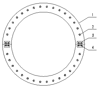
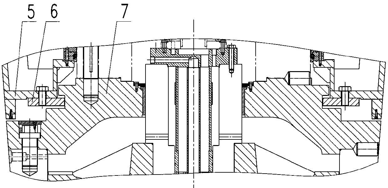
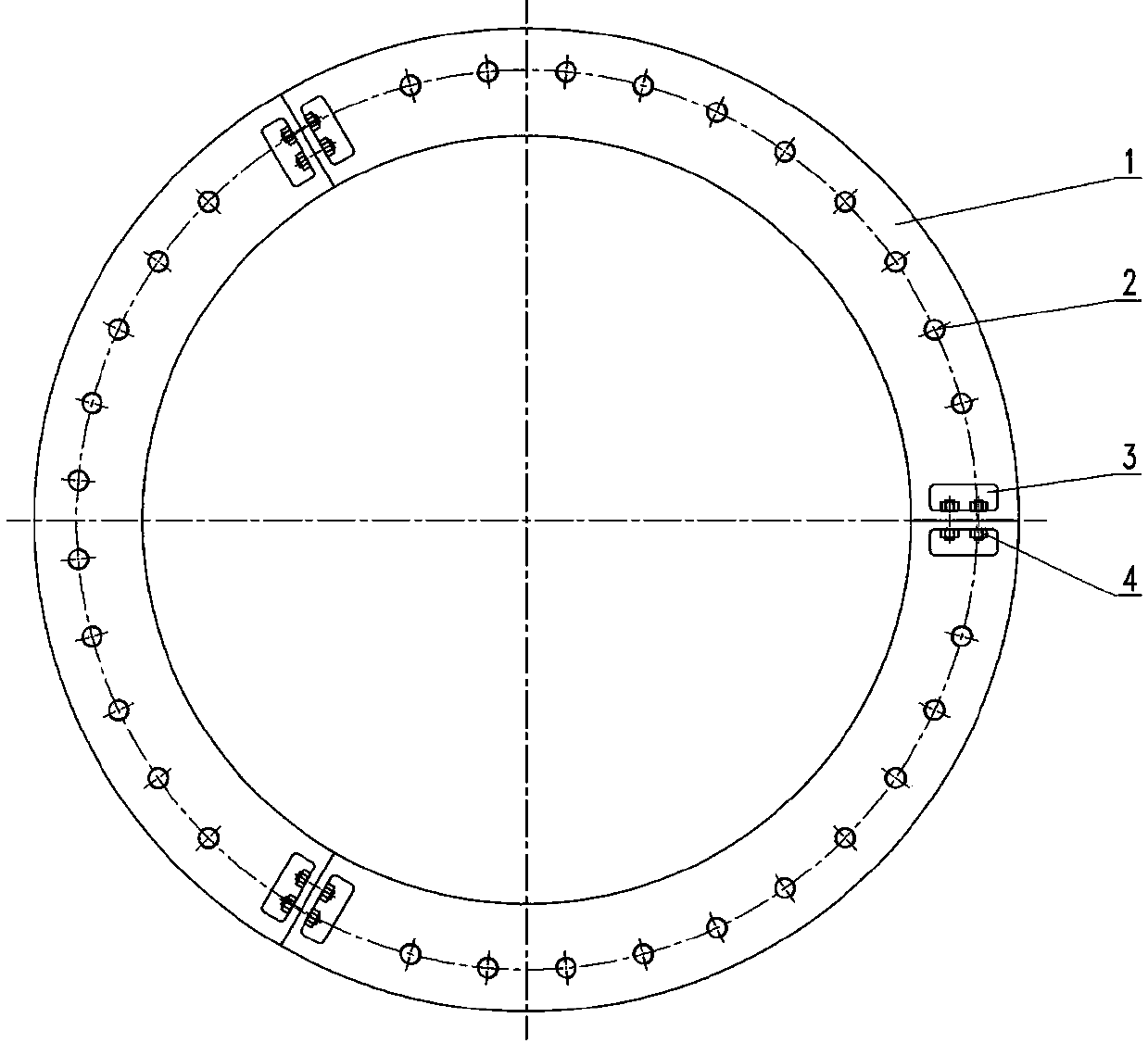
[0066] The hoisting and suspension retaining ring of the runner of the axial-flow paddle-type water turbine of this embodiment is composed of two arc-shaped retaining ring bodies that are connected end to end into a ring shape. The retaining ring body is evenly distributed to connect the retaining ring body and the turbine guide cone. Screw holes; both ends of the snap ring body are provided with an inner excavation cavity, and the inner excavation cavity is provided with a connecting piece that connects the two snap ring bodies. The connecting piece in this embodiment is a bolt. The principle of this embodiment is that a ring groove is machined on the outer edge of the cylinder head of the runner servomotor as a snap ring and the runner suspension stress area; a screw hole is machined on the flange surface of the lower part of the deflector cone for gripping The snap ring is combined with the deflector cone into one body. As it should be, the inner diameter of the snap ring sh...

Embodiment 2

[0069] The hoisting and suspension snap ring of the runner of the axial-flow paddle water turbine of this embodiment includes a three-lobed arc-shaped snap ring body, and the snap ring body is evenly distributed with screw holes for connecting the snap ring body and the turbine guide cone. The method of use in this embodiment is to machine a ring groove on the outer edge of the cylinder head of the runner servomotor, which serves as a snap ring and the runner suspension stress area; machine a screw hole on the flange surface of the lower part of the deflector cone for Close the snap ring to combine it with the guide cone; when using it, first snap the three snap ring bodies into the ring groove of the runner servo cylinder head, and then use the screw holes to guide the snap ring and the turbine. Cone. As it should be, the inner diameter of the snap ring should be matched with the ring groove of the runner servomotor cylinder head; in order to align the snap ring with the defle...

Embodiment 3

[0071] The hoisting and suspension snap ring of the runner of the axial-flow paddle-type water turbine of this embodiment is formed by connecting the four-petal arc snap ring body end to end into a ring shape. The snap ring body is evenly distributed with the snap ring body and the turbine guide cone. Screw holes; both ends of the snap ring body are provided with an inner excavation cavity, and the inner excavation cavity is provided with a connecting piece that connects the two snap ring bodies. The connecting piece in this embodiment is a bolt. The principle of this embodiment is that a ring groove is machined on the outer edge of the cylinder head of the runner servomotor as a snap ring and the runner suspension stress area; a screw hole is machined on the flange surface of the lower part of the deflector cone for gripping The snap ring is combined with the deflector cone into one body. As it should be, the inner diameter of the snap ring should be matched with the ring groo...


PUM


Abstract

The invention discloses an axial-flow kaplan turbine rotating-wheel hoisting and suspension snap ring. The axial-flow kaplan turbine rotating-wheel hoisting and suspension snap ring solves the problem that the existing axial-flow kaplan turbine rotating-wheel hoisting and suspension method has complex processes and is inconvenient for operation. The axial-flow kaplan turbine rotating-wheel hoisting and suspension snap ring comprises at least two arc-shaped snap ring bodies and the snap ring bodies are uniformly provided with screw holes for combining the snap ring bodies and a kaplan turbine diversion cone. The axial-flow kaplan turbine rotating-wheel hoisting and suspension snap ring has a simple structure, is free of tooling holes of a base ring and blade main bodies, is free of a concave ring groove or a raised ring belt of a main shaft, can be simply and conveniently operated, saves many processes, and greatly improves set installation and unkeep work efficiency.

Description

Technical field [0001] The invention belongs to the field of axial-flow paddle-type water turbines, and specifically relates to a method for hoisting and hanging the runner of an axial-flow paddle-type water turbine. The invention is suitable for all axial-flow turbines, and is especially suitable for existing units before the transformation. The hoisting and suspension of the runner is realized by the base ring, and the axial flow turbine unit with the number of blades changed after the transformation. Background technique [0002] There are two main methods for hoisting and suspension of the existing water turbine runner. One is to simultaneously open a gripping hole on the base ring and the blade handle of the runner blade to install the suspension runner tie rod tool (mainly for large axial flow turbines) ; The second is to process concave ring grooves or raised ring belts on the main shaft of the turbine, and use the screw holes of the bearing bracket on the support cover to...

Claims


Application Information

Patent Timeline
Patent Type & Authority Applications(China)
IPC IPC(8): B66C1/22
Inventor 王继娥代继江曾明富
Owner DONGFANG ELECTRIC MACHINERY
Why Eureka
Try Eureka