
a vacuum furnace

A vacuum furnace and vacuum system technology, applied in heat treatment equipment, quenching devices, manufacturing tools, etc., can solve the problems of difficulty in obtaining vacuum, adsorption on the wall of the quenching pool, weakening the strength and toughness of metal materials, etc.

Active Publication Date: 2016-06-08
东莞市禾盛金属科技有限公司 +2
View PDF8 Cites 0 Cited by
  • Summary
  • Abstract
  • Description
  • Claims
  • Application Information

AI Technical Summary

Problems solved by technology

However, this multi-purpose furnace still has the following disadvantages: (1) Oxygen in the atmosphere in the furnace can easily cause grain boundary oxidation on the parts being heated. The longer the heating time, the deeper the oxidation, and this grain boundary oxidation will sharply weaken the metal material. Strength and toughness, reducing the performance of metal parts
[0006] The disadvantage of the current vacuum furnace is that it can only be quenched with oil or high-pressure gas, and its cooling rate is limited
However, if the ordinary vacuum furnace is directly replaced with a water-soluble quenching medium for quenching, the problems faced are 1) under vacuum and negative pressure, the water-soluble quenching medium will evaporate in large quantities, forming a water-containing atmosphere. It will enter the heating chamber and cause oxidative damage to the heating chamber in the high temperature state; 2) After quenching, a large amount of water vapor is adsorbed on the wall of the pre-cooling chamber, and after the quenching liquid is discharged, there are droplets adsorbed on the wall of the quenching pool, Difficult to obtain a good vacuum with conventional vacuum pump systems

Method used


Image

  • a vacuum furnace
  • a vacuum furnace
  • a vacuum furnace

Examples


Embodiment Construction

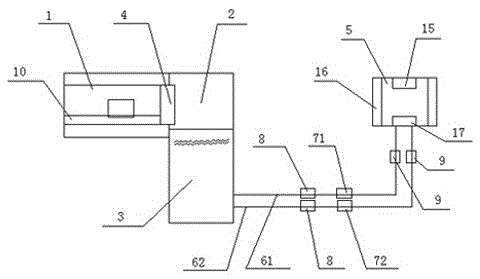
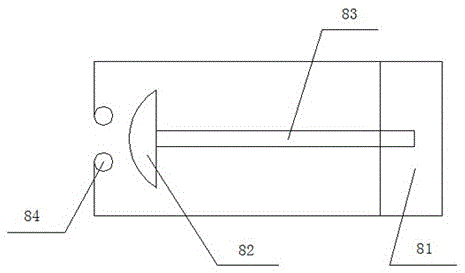
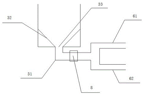
[0022] In this example, refer to Figure 1 to Figure 5 Shown, a kind of vacuum furnace, it comprises quenching pool 3 and precooling chamber 2 and the heating chamber 1 that is connected with precooling chamber 2, is provided with insulation door 4 between described heating chamber 1 and precooling chamber 2; The quenching pool 3 is connected with a preparatory bin 5, and a quenching liquid drain pipe 61 and a quenching liquid return pipe 62 are arranged between the quenching pool 3 and the preparatory bin 5; the quenching liquid drain pipe 61 and the quenching liquid return pipe 62 is respectively provided with a drain pump 71 and a liquid return pump 72; a baffle valve 8 is connected between the liquid drain pump 71 and the quenching pool 3; a valve 8 is connected between the liquid return pump 72 and the quenching pool 3 The baffle valve 8, the baffle valve 8 has effectively prevented the quenching liquid in the preparatory bin 5 from flowing back to the quenching pool 3; a...


PUM


Abstract

A vacuum furnace of the present invention comprises a quenching pool, a pre-cooling chamber, and a heating chamber connected to the pre-cooling chamber, an insulated door is arranged between the heating chamber and the pre-cooling chamber; the quenching pool is connected with a preparatory warehouse, A quenching liquid discharge pipe and a quenching liquid return pipe are arranged between the quenching pool and the reserve chamber; a liquid discharge pump and a liquid return pump are respectively arranged on the quenching liquid discharge pipe and the quenching liquid return pipe; A baffle valve is connected between the drain pump and the quenching pool; a baffle valve is connected between the liquid return pump and the quenching pool; a filter is connected between the liquid drain pump and the reserve chamber; the liquid return A filter is provided in the connection between the pump and the reserve chamber. The vacuum furnace of the present invention uses water-based quenching liquid, high quenching cooling speed, high material hardenability, high production efficiency and low production cost.

Description

technical field [0001] The invention relates to a vacuum furnace. Background technique [0002] Existing vacuum quenching furnaces commonly used in the heat treatment industry include oil quenching furnaces and high-pressure gas quenching furnaces. When the vacuum furnace is quenched with oil and gas, the quenching cooling rate is limited by the cooling characteristics of oil or high-pressure gas. For those materials (or parts with large dimensions) that require high cooling rate or low hardenability, qualified quenching quality cannot be obtained. As a result, the use of vacuum furnaces is limited. [0003] If a water-soluble quenching medium is used for quenching in a general vacuum furnace, the water vapor generated under vacuum and low pressure will enter the heating chamber, which will damage the heating chamber made of carbon fiber due to strong oxidation at high temperature. [0004] For occasions that require high cooling speed or high hardenability, the industry u...

Claims


Application Information

Patent Timeline
Patent Type & Authority Patents(China)
IPC IPC(8): C21D1/63C21D1/773
Inventor 刘小阳
Owner 东莞市禾盛金属科技有限公司
Learn More