
A portable power head core drilling rig

A technology of core drilling rig and power head, which is applied in the direction of rotary drilling rig, percussion drilling, rotary drilling, etc. It can solve the problems of low work efficiency, large swing range of drill pipe, and poor rock drillability, etc., and achieves The disassembly and assembly of the power head is convenient, the installation and disassembly are convenient, and the effect of prolonging the service life

Active Publication Date: 2017-01-04
四川诺克钻探机械有限公司
View PDF7 Cites 0 Cited by
  • Summary
  • Abstract
  • Description
  • Claims
  • Application Information

AI Technical Summary

Problems solved by technology

[0002] Existing core drilling rigs mainly include vertical-axis drilling rigs and full hydraulic power head drilling rigs. Although vertical-axis drilling rigs can drill holes with small inclination angles, it is difficult to satisfy inclined hole drilling with large inclination angles and a wide range of angle changes. The vertical shaft drilling rig is large in size and heavy, which is not conducive to handling, installation and disassembly. Therefore, the full hydraulic power head drilling rig overcomes the above-mentioned shortcomings of the vertical shaft drilling rig and is widely used in harsh environments such as the field and mountainous areas.
[0003] However, as the drilling depth increases and the rock drillability becomes poor, there are many problems in the existing power head drilling machine. The rod is difficult to lift, resulting in low work efficiency; at the same time, the service life of the power head is severely shortened due to the excessive swing of the drill rod

Method used


Image

  • A portable power head core drilling rig
  • A portable power head core drilling rig
  • A portable power head core drilling rig

Examples


Embodiment Construction

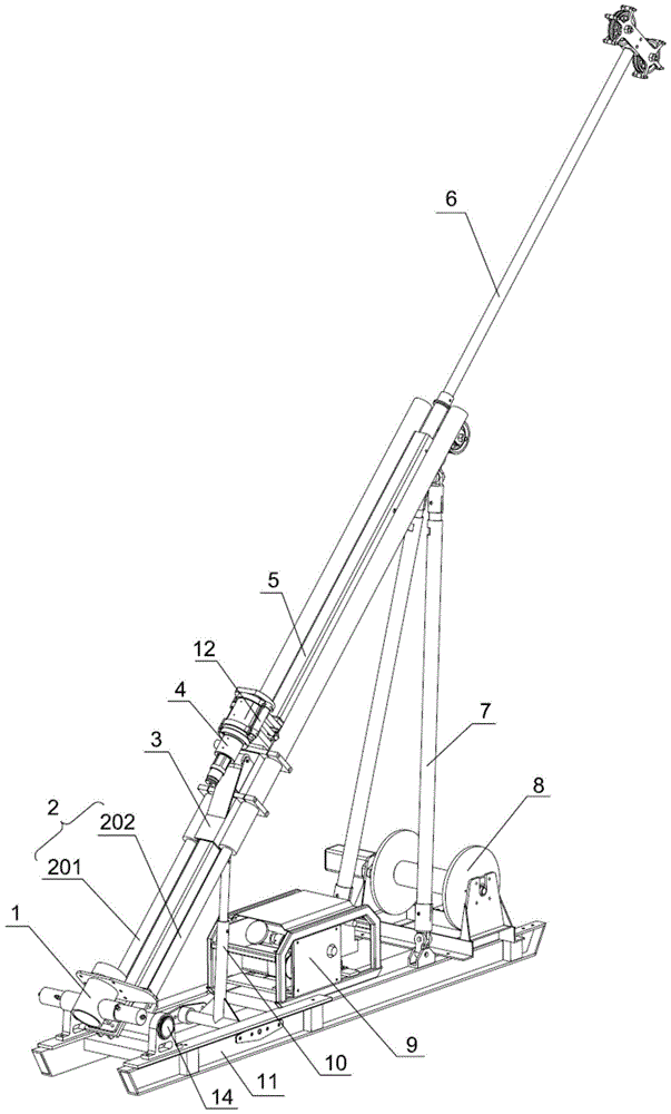
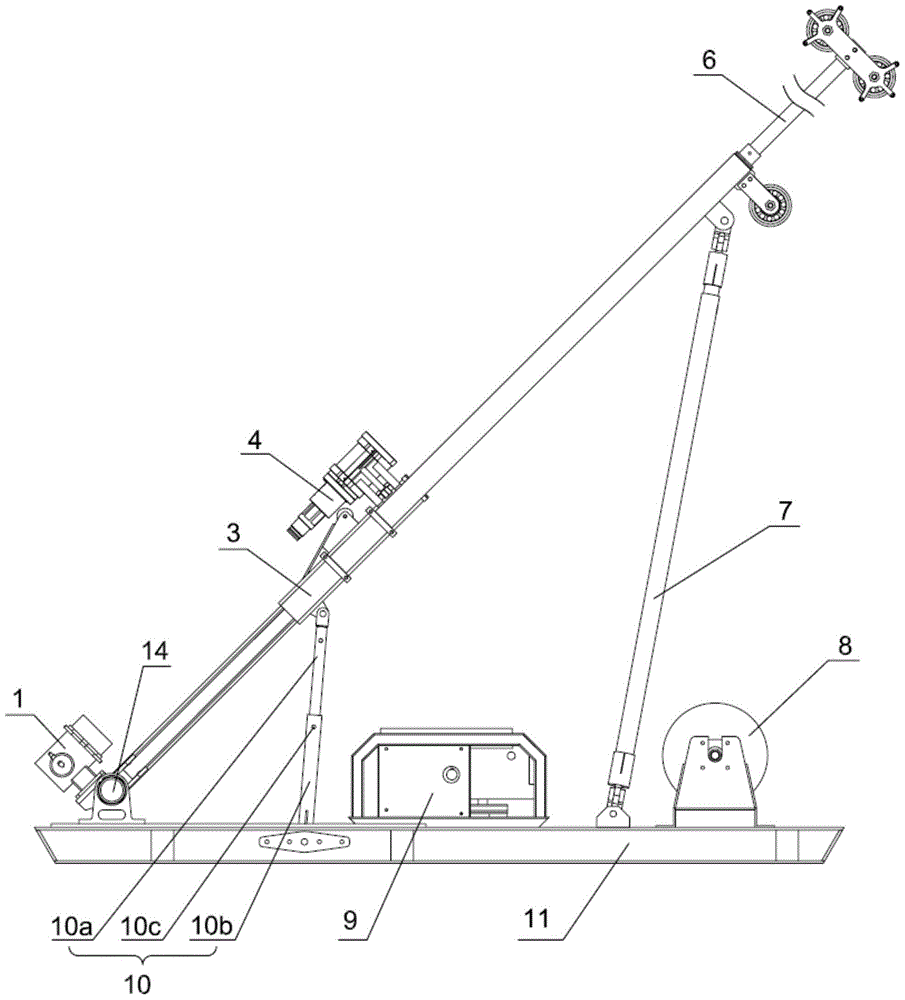
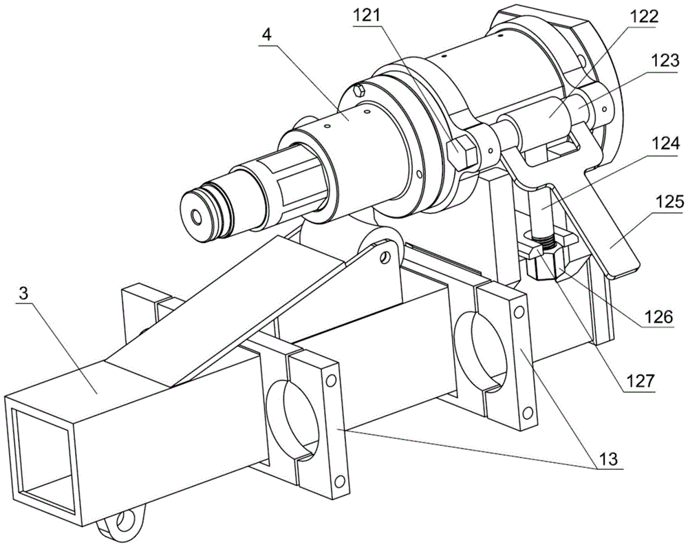
[0036] refer to figure 1 , figure 2 , a portable power head core drilling rig of the present invention, including: double rail base 11, guide rail 5, sliding sleeve 3, power head 4, mast 6, support rod, holder 1 and lifting cylinder 2. A mud pump 9 and a hoist 8 are also arranged on the double-track base 11 . One end of the guide rail 5 is fixedly connected to the rotating shaft 14 , and is connected to the double-rail base 11 through the rotating shaft 14 , and the guide rail 5 can rotate around the rotating shaft 14 . A movable sliding sleeve 3 is set on the guide rail 5, and a power head 4 is installed on the sliding sleeve 3 through a locking device 12. A lifting cylinder 2 is arranged between the sliding sleeve 3 and the rotating shaft 14 to drive the sliding sleeve 3 to slide along the guide rail 5. The mast 6 is fixedly connected with the other end of the guide rail 5 , and the mast 6 has a fixed double support pulley 601 and a movable single support pulley 602 . Th...


PUM


Abstract

The invention discloses a portable core drilling rig with a power head, which comprises: a double-rail base, a guide rail, a sliding sleeve, a power head, a mast, a support rod, a clamper and a lifting oil cylinder, and the power head is installed and fixed on the sliding sleeve through a locking device. The mast is fixedly connected to the other end of the guide rail. The mast has fixed double support pulleys and a movable single support pulley; the support rod includes a main support rod and an auxiliary support rod, and the main support rod is respectively hinged between the end of the guide rail and the double-rail base. The auxiliary support rod is lapped between the guide rail and the double-rail base when the tower is lifted; the clamper includes the clamper body and the drill pipe stabilization ring, the drill pipe stabilization ring is composed of a stable bearing seat and a stable bearing ring, and the stable bearing seat and clamp One end of the holder body is fixedly connected, and the stabilizing bearing ring is installed in the stabilizing bearing seat, and the inner diameter of the stabilizing bearing ring is 1 to 2 mm larger than the outer diameter of the drill pipe. The portable power head rock core drilling machine of the present invention is convenient to disassemble and carry, and the drill pipe runs stably.

Description

technical field [0001] The invention belongs to the technical field of drilling equipment, and in particular relates to a portable power head core drilling machine. Background technique [0002] Existing core drilling rigs mainly include vertical-axis drilling rigs and full hydraulic power head drilling rigs. Although vertical-axis drilling rigs can drill holes with small inclination angles, it is difficult to satisfy inclined hole drilling with large inclination angles and a wide range of angle changes. The vertical shaft drilling rig is bulky and heavy, which is not conducive to handling, installation and disassembly. Therefore, the fully hydraulic power head drilling rig overcomes the above-mentioned shortcomings of the vertical shaft drilling rig and is widely used in harsh environments such as the field and mountainous areas. [0003] However, as the drilling depth increases and the rock drillability becomes poor, there are many problems in the existing power head drill...

Claims


Application Information

Patent Timeline
Patent Type & Authority Patents(China)
IPC IPC(8): E21B3/02E21B19/10E21B19/00
Inventor 腾飞娄和康尹立蔡新民蔡平基
Owner 四川诺克钻探机械有限公司
Learn More