Positioning assembly for electronic device

A technology for electronic devices and positioning components, applied to electrical components, circuits, telephone structures, etc., to achieve the effects of reducing friction, simplifying the number of configurations, and saving production costs

Inactive Publication Date: 2014-12-03
SUPERMAX +1
View PDF5 Cites 12 Cited by
  • Summary
  • Abstract
  • Description
  • Claims
  • Application Information

AI Technical Summary

Problems solved by technology

For example, when a tablet computer is used for document processing or reading at home or in the office, it is usually placed at a vertical angle, while it is placed horizontally when it is carried in the car to watch movies or multimedia, so that it is often necessary to operate the tablet computer or mobile phone. It can be positioned and disassembled at any time, and can be rotated and adjusted between the two angles, but the current commercially available products obviously cannot meet this demand

Method used


Image

  • Positioning assembly for electronic device
  • Positioning assembly for electronic device
  • Positioning assembly for electronic device

Examples


Embodiment Construction

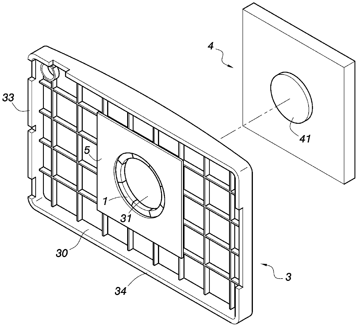
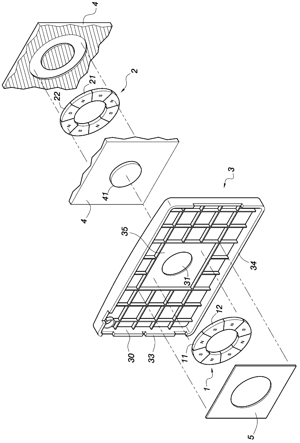
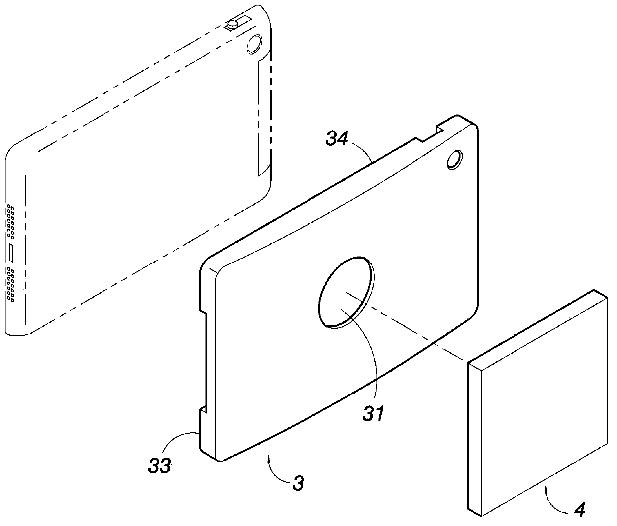
[0044] Please refer to Figure 1 to Figure 7 , revealing the drawings of the first embodiment of the present invention, wherein, figure 1 It is a schematic perspective view of the configuration of a preferred embodiment of the present invention, figure 2 for figure 1 three-dimensional exploded view, image 3 for figure 1 A stereogram from another perspective, Figure 4 for figure 1 A cutaway view of an embodiment, Figure 5 for Figure 4 The perspective view of the first and second multi-pole magnetic units of the embodiment, Image 6 for Figure 4 The cutaway diagram of the use state, Figure 7 for Image 6 A perspective view of the first and second multi-pole magnetic units of the embodiment.

[0045] A positioning component of an electronic device according to the present invention is illustrated by the above drawings, which includes a housing 3 that can be fixed on the back of the electronic device and is provided with a first multi-pole magnetic unit 1, and a ...


PUM


Abstract

The present invention is a positioning assembly for an electronic apparatus, and is about a positioning assembly for rapidly positioning and disassembling an electronic apparatus by means of the characteristics of magnetic adsorption and repulsion to make the electronic apparatus portable and available at any time. The positioning assembly structurally comprises a shell, which can be fixed on the back of the electronic apparatus and is provided with a first multi-polar magnetic unit, and a support member, which is internally provided with a second multi-polar magnetic unit, wherein the magnetic poles of the second multi-polar magnetic unit of the support member and the first multi-polar magnetic unit are arranged in such a manner that the magnetic poles with opposite magnetisms are corresponding to each other, enabling the first multi-polar magnetic unit to be adsorbed onto the second multi-polar magnetic unit at a particular angle and also enabling the shell to be positioned on the support member under strong adsorption; and when the shell is rotated by an angle, the first multi-polar magnetic unit and the second multi-polar magnetic unit are mutually repulsive, so that the shell can be separated rapidly to thereby improve the convenience in use.

Description

technical field [0001] The invention relates to a positioning component that adopts a magnetic attraction method to quickly locate and disassemble an electronic device, so as to facilitate carrying, accessing, and viewing multimedia images and video at any time. Especially for electronic devices such as mobile phones, tablet computers, digital photo frames, driving recorders, monitors, displays, etc., and relates to a device that can magnetically adsorb and position the electronic devices at a specific angle, or repel each other in a deflected manner so that the A positioning component for separation and removal of electronic devices. Background technique [0002] In recent years, with the rapid development of the electronics industry, technology is changing with each passing day, and information products are constantly being introduced. New types of portable electronic devices such as PDA, Personal Digital Assistant), digital photo frame or driving recorder make life more ...

Claims


Application Information

Patent Timeline
Patent Type & Authority Applications(China)
IPC IPC(8): F16M11/04F16M13/02
CPCH04M1/04G06F1/1628H01F7/0252
Inventor 徐永珑
Owner SUPERMAX
Why Eureka
Try Eureka