Direct heat accumulation system for heat supply network and heat accumulation and release method for direct heat accumulation system

A heat storage system and heat network technology, applied to heating systems and central heating, can solve problems such as the heat storage and release method of the direct heat storage system, and achieve stable operation by solving the contradiction between time and space. Working conditions, the effect of mitigating the fluctuation of heating demand

Inactive Publication Date: 2014-12-03
HUADIAN ELECTRIC POWER SCI INST CO LTD
View PDF5 Cites 10 Cited by
  • Summary
  • Abstract
  • Description
  • Claims
  • Application Information

AI Technical Summary

Problems solved by technology

[0004][Dissertation] Wang Wei, 2010-Beijing University of Technology: Architecture and Civil Engineering published research on the application of heat accumulators in the field of district heating. The research pointed out that The introduction of heat accumulators in the district heating system not only plays a significant role in energy saving and emission reduction, but also can enhance the stability and safety of the heating network operation. However, the direct heat storage system applied to the heating network is not given in this study and heat storage method
[0005] To sum up, there is currently no application with a reasonable structural design that enables the heating network system to achieve optimal operation and improve the stability and safety of the heating system Direct heat storage system of heat network and heat storage and release method

Method used


Image

  • Direct heat accumulation system for heat supply network and heat accumulation and release method for direct heat accumulation system
  • Direct heat accumulation system for heat supply network and heat accumulation and release method for direct heat accumulation system

Examples


Embodiment Construction

[0018] The present invention will be further described in detail below in conjunction with the accompanying drawings and examples. The following examples are explanations of the present invention and the present invention is not limited to the following examples.

[0019] Example.

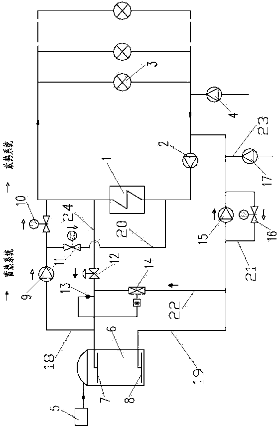
[0020] see figure 2 In this embodiment, the direct heat storage system applied to the heat network includes the first heat exchange station 1, the primary heat network circulation pump 2, the heat exchange station 3, the primary network side make-up water pump 4, the nitrogen making device 5, the heat storage tank 6, Upper distribution water tray 7, lower distribution water tray 8, heat release pump 9, exothermic hot water control valve a10, exothermic hot water control valve b11, heat storage decompression valve 12, storage water temperature tester 13, mixing regulating valve 14 , heat storage pump 15, heat release cold water control valve 16, heat storage side supplementary water pump 17, heati...


PUM


Abstract

The invention relates to a direct heat accumulation system for a heat supply network and a heat accumulation and release method for the direct heat accumulation system. The direct heat accumulation system includes a nitrogen-making device, a heat accumulation tank, an upper water distribution disk, a lower water distribution disk, a heat release pump, a heat release hot water control valve a, a heat release hot water control valve b, a heat accumulation reducing valve, a heat accumulation water temperature tester, a mixing regulating valve, a heat accumulation pump, a heat release cold water control valve, a heat supply network water supply pipeline, a heat supply network water return pipeline, a high temperature water supply pipe, a cold water pipe, a heat supply network water supply and water return connecting pipeline and a heat accumulation pipeline, wherein the nitrogen-making device is connected with the top of the heat accumulation tank; the upper water distribution disk and the lower water distribution disk are mounted at the top and the bottom of the heat accumulation tank respectively; one end of the heat supply network water supply pipeline is connected onto the upper water distribution disk; one end of the heat accumulation pipeline is connected onto the heat supply network water supply pipeline; one end of the heat supply network water return pipeline is connected onto the lower water distribution disk; the heat accumulation pump is mounted on the heat supply network water return pipeline; one end of the heat supply network water supply and water return connecting pipeline is connected onto the heat accumulation pipeline. According to the invention, the structural design is reasonable, the operation stability and safety of the heat supply system are improved.

Description

technical field [0001] The invention relates to a direct heat storage system applied to a heating network and a heat storage and release method thereof, and belongs to a peak-shaving heat storage system and a heat storage method applied to central heating. Background technique [0002] With the gradual improvement of people's living standards, the heat demand is also rising. Although some advanced energy-saving and consumption-reducing technologies have been widely used in power plants and have produced good economic and social benefits, they still cannot meet the increasing heat demand and thermal comfort of the society. [0003] The traditional heating network system is attached figure 1 As shown, it is mainly composed of the first heating station 1, the circulation pump 2 of the primary heating network, the heat exchange station 3 and the supplementary water pump 4 on the primary network side. When the heating demand of heat users corresponding to the heat exchange stat...

Claims


Application Information

Patent Timeline
Patent Type & Authority Applications(China)
IPC IPC(8): F24D11/00F24D19/10
Inventor 何晓红陈菁孙士恩李善化俞聪赵明德舒斌常浩
Owner HUADIAN ELECTRIC POWER SCI INST CO LTD
Why Eureka
Try Eureka