Fertilizer Application System Using Pneumatic Conveying With Large Diameter Lines And Rotary Distributor

a technology of pneumatic conveying and fertilizer application system, which is applied in the field of agricultural products delivery system, can solve the problems of time-consuming and inconvenient, the metering system itself is a complex mechanism, and the different rate of particulate material being dispensed

Active Publication Date: 2018-12-06
CNH IND CANADA
View PDF1 Cites 2 Cited by
  • Summary
  • Abstract
  • Description
  • Claims
  • Application Information

AI Technical Summary

Benefits of technology

The present invention is an applicator that uses a pneumatic conveying system to transfer particulate material from containers to application equipment on demand. The system includes individual distribution channels that allow for independent control of the particulate material distribution across different sections of the booms. The lines are connected to the chambers of the tank through a metering system that maintains air pressure within the lines. The rotation of the airlocks can be controlled to adjust the speed at which the particulate material is dispensed from the chambers, making it possible to adapt to varying operational conditions. The technical effect of this invention is the ability to control the distribution of particulate material in an application equipment with greater precision and accuracy.

Problems solved by technology

This has been difficult due to the necessary metering systems for applying the different materials.
This can be time consuming and inconvenient if the metering device is underneath the tank.
While the use of a metering system can effectively distribute the different particulate material to the various distribution channels and nozzles of the applicator, the metering system itself is a complex mechanism that must be accurately operated in order to effectively distribute the particulate matter to each nozzle and to accommodate for operational changes including additional particulate material(s) to be dispensed, sectional control and turning compensations, among others.
Further, with pneumatic delivery systems, the pressure drop across various portions of the delivery system can often result in different rates of the particulate material being dispensed from different channels and nozzles.

Method used


Image

  • Fertilizer Application System Using Pneumatic Conveying With Large Diameter Lines And Rotary Distributor
  • Fertilizer Application System Using Pneumatic Conveying With Large Diameter Lines And Rotary Distributor
  • Fertilizer Application System Using Pneumatic Conveying With Large Diameter Lines And Rotary Distributor

Examples


Embodiment Construction

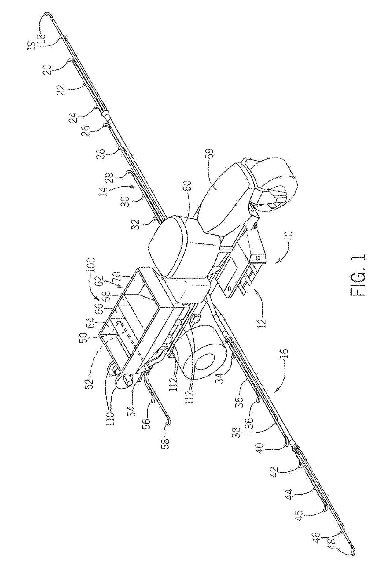
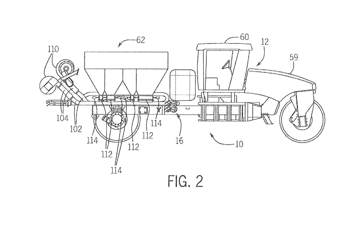
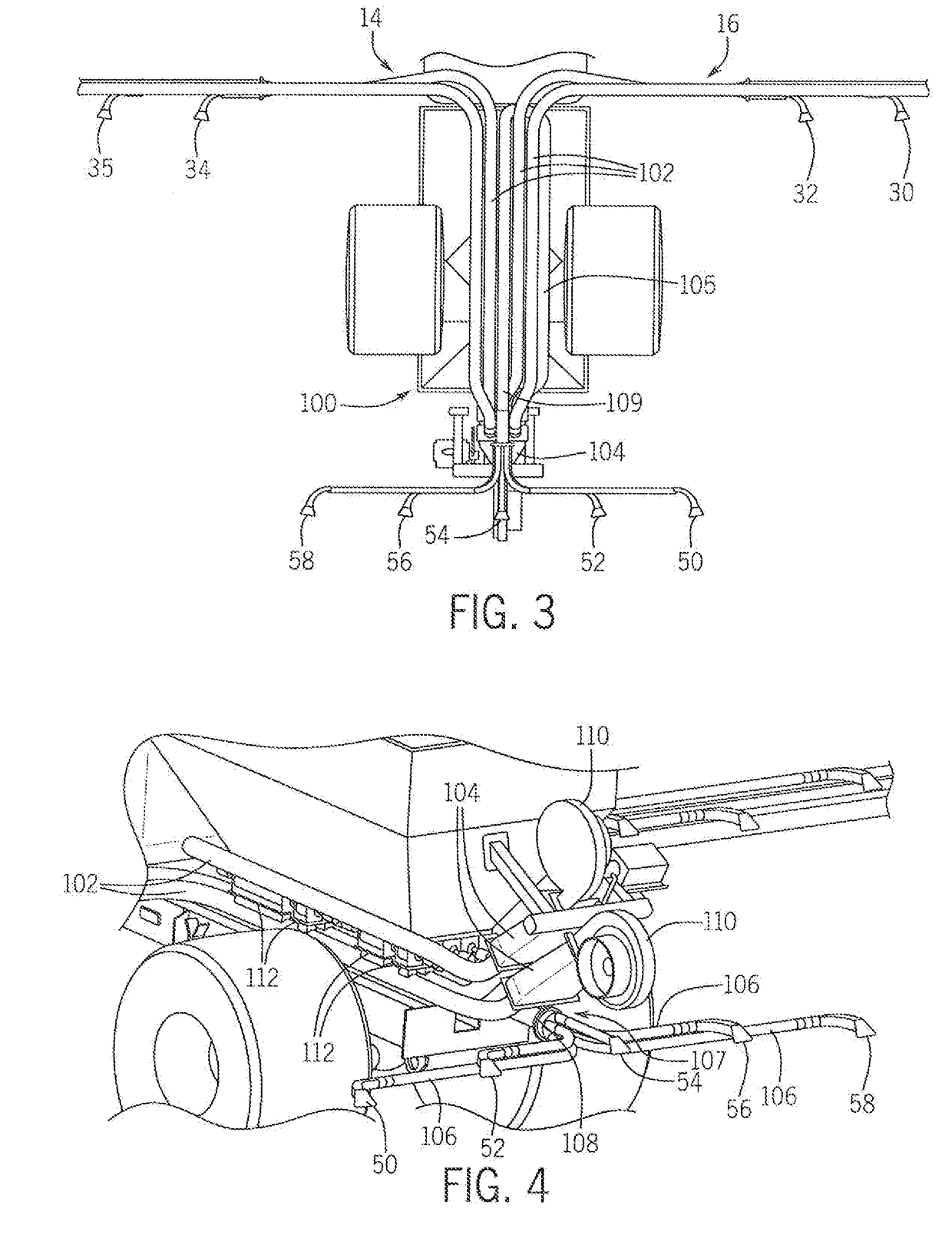
[0021]Referring now to the drawings, and more particularly to FIGS. 1-3, there is shown an agricultural application implement 10, on which a pneumatic conveying system 100 can be used. In the exemplary embodiment shown, application implement 10 is a granular fertilizer applicator 10. As is known in the art, applicator 10 generally includes a large tired transport unit 12 such as truck or tractor, and laterally extending particle delivery booms 14 and 16, which may be pivoted to a stowed position close to the implement for storage or transport. Each boom 14, 16 includes a plurality of boom tubes or conduits terminating at the outboard end in a particle delivering unit, which for fertilizer applicator 10 are a spreading outlet or nozzle. In the exemplary embodiment shown, boom 14 includes ten nozzles 18, 19, 20, 22, 24, 26, 28, 29, 30 and 32; and boom 16 includes ten nozzles 34, 35, 36, 38, 40, 42, 44, 45, 46 and 48. Additionally, at the back of applicator 0 there are five rear nozzle...


PUM


Abstract

The present invention is directed to an applicator having an agricultural product pneumatic conveying system which meters particulate material from one or more source containers at the application equipment and transports the particulate material to evenly distribute the particulate material from the applicator. The pneumatic conveying system employs large diameter supply lines connected between the metering devices at the source containers and delivery nozzles, where the supply lines operate to move and mix the particulate material from the source containers to the nozzles. The particulate material is metered from the source containers into the supply lines via a number of airlocks that can be operated without allowing airflow from the large diameter supply lines to enter the source containers through the airlocks. In addition, the metering devices can b e operated in collective or independent variable manners to allow for sectional control and turning compensation.

Description

FIELD OF THE DISCLOSURE[0001]The present invention relates generally to agricultural equipment, and, more particularly, to an agricultural product delivery system on an application implement, such as a planter, seeder or fertilizer application equipment, for applying particulate material such as seed, fertilizer, herbicide or insecticide in a field, either as a surface application or deposited in the soil to improve soil quality.BACKGROUND OF THE DISCLOSURE[0002]Agricultural product delivery systems are known to utilize various mechanisms, including mechanical and pneumatic systems, i.e., a flow of air, to assist in the delivery and movement of particulate material or product such as fertilizer, seed, insecticide or herbicide from a product supply chamber through an interior passage provided by a series of elongate tubes which extend from the product supply chamber to a product applicator that places the product on or in growing medium, such as soil. Such agricultural product delive...

Claims


Application Information

Patent Timeline
Patent Type & Authority Applications(United States)
IPC IPC(8): A01C15/14A01C15/04A01M9/00A01C7/08A01C15/00
CPCA01C15/14A01C15/04A01C15/006A01C7/08A01M9/0084A01M7/0082A01C21/005
Inventor ROBERGE, MARTIN J.DENIS, JOELRUPPERT, REX L.
Owner CNH IND CANADA
Why Eureka
Try Eureka