Rotating shaft angle position sensing device and sensing system

A technology of angular position and sensing system, which is applied in the direction of measuring devices, electrical devices, instruments, etc., can solve the problems affecting the sensing accuracy and sensitivity of sensing circuits, the change of magnetic field strength of interfering magnets, and the adverse effects of assembly tolerances, etc., to achieve Improve sensing accuracy and sensitivity, eliminate signal asynchrony, and extend the range of use

Active Publication Date: 2014-12-03
TYCO ELECTRONICS (SHANGHAI) CO LTD +1
View PDF9 Cites 15 Cited by
  • Summary
  • Abstract
  • Description
  • Claims
  • Application Information

AI Technical Summary

Problems solved by technology

First, because there is a magnetic field source in the surrounding environment of the gear selection linkage rod, it may interfere with the change of the magnetic field strength generated by the magnet when it rotates, thus affecting the sensing accuracy and sensitivity of the sensing circuit
Second, because the axial displacement and vibration of the magnetic pole along the rotating shaft will also affect the sensing accuracy and sensitivity of the sensing circuit
Because the two ICs are placed side by side, the two ICs sense different magnetic field strengths, and such an arrangement can adversely affect the assembly tolerances (or tolerances) of the sensing system

Method used


Image

  • Rotating shaft angle position sensing device and sensing system
  • Rotating shaft angle position sensing device and sensing system
  • Rotating shaft angle position sensing device and sensing system

Examples


Embodiment Construction

[0036] Reference will now be made to specific embodiments, examples of which are illustrated in the accompanying drawings. In the detailed description of particular embodiments, directional terms such as "top", "bottom", "above", "below", "left", "right", etc. are used with reference to the directions described in the drawings. Since components of embodiments of the present invention may be arranged in many different orientations, directional terms are used for purposes of illustration and are not limiting in any way. Wherever possible, the same or similar numerals and symbols are used throughout the drawings to refer to the same or like parts.

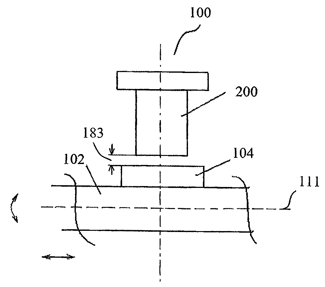
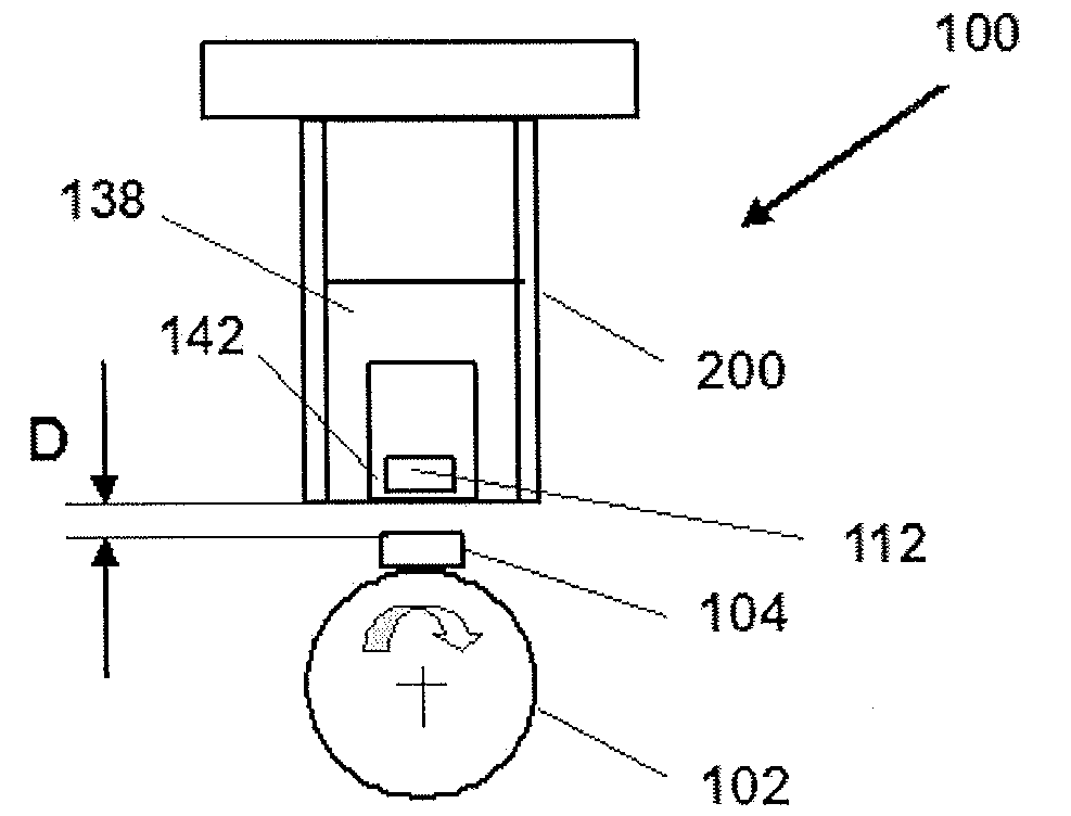
[0037] Figures 1A-1BA sensing system 100 for sensing the angular position of the rotating shaft 102 according to the present invention and a schematic installation diagram of the sensing system 100 relative to the rotating shaft 102 and the magnetic block 104 are described.

[0038] Such as Figure 1A As shown, the angular position...


PUM


Abstract

The invention provides a sensor for sensing an angle position of a rotating shaft and a sensing system, wherein a magnet conductive block is fixedly arranged on the rotating shaft and can rotate along with rotation of the rotating shaft. The sensor comprises a magnet device and a Hall effect sensing component. The Hall effect sensing component is used for sensing the angle position of the rotating shaft. When the magnet conductive block rotates along with the rotating shaft, a magnetic field which is generated by the magnet device is changed. The Hall effect sensing component generates an electric signal along with magnetic field change. The electric signal indicates the angle position of the rotating shaft. Because built-in U-shaped back magnet technology is adopted for the sensor of the invention, sensing precision of the sensor is greatly improved. Therefore a precision requirement for measuring the angle position of the rotating shaft can be satisfied through using a single IC chip which is provided with one Hall effect sensing component.

Description

technical field [0001] The present invention generally relates to a sensing device and a sensing system for the angular position of a rotating shaft, and more particularly relates to a sensing device and a sensing system for detecting the angle of a rotating shaft by sensing changes in magnetic field strength. Background technique [0002] It is known in the industry to detect angular position of a rotating shaft by sensing changes in a magnetic field. Generally speaking, the sensing system for the angular position of the existing rotating shaft includes a magnet and a sensing circuit; wherein the magnet is installed on the rotating shaft (such as on the gear selection link in the gearbox), and the rotating shaft can rotate around its axis, It can also move along its axial direction, and the sensing circuit is separately arranged adjacent to the magnet. In this way, the magnet rotating with the rotation of the rotating shaft produces a change in magnetic field strength at t...

Claims


Application Information

Patent Timeline
Patent Type & Authority Applications(China)
IPC IPC(8): G01B7/30
Inventor 程达伟林斐何赛德-奥利弗·萨尔瓦多
Owner TYCO ELECTRONICS (SHANGHAI) CO LTD
Why Eureka
Try Eureka