A device that can detect the motion state of the ball in the rolling kinematic pair

A technology of balls in the motion state and pair, which is applied in the direction of measuring/indicating equipment, machine gear/transmission mechanism testing, metal processing machinery parts, etc., can solve the problem of loss of pre-tightening force, degradation of rolling motion pair precision, and inability to directly observe the ball Running status and other issues, to achieve the effect of simple structure and easy manufacture

Inactive Publication Date: 2016-06-22
BEIJING UNIV OF TECH
View PDF4 Cites 0 Cited by
  • Summary
  • Abstract
  • Description
  • Claims
  • Application Information

AI Technical Summary

Problems solved by technology

After the rolling kinematic pair actually works for a period of time, the friction and wear of the moving parts will lead to the loss of pre-tightening force and the degradation of the accuracy of the rolling kinematic pair. It is very important to analyze the accuracy degradation process of the rolling kinematic pair, and wear is one of the main reasons for the degradation of accuracy. You must know For the wear mechanism of the ball and the guide rail, it is necessary to know the motion state of the ball in the guide rail. Due to the asymmetry of the mechanism, the change of the contact angle and the preload, the movement form of the ball in the guide rail is very complicated, and in different The balls have different motion forms under loading conditions, and the ball guide is a closed space, we cannot directly observe the running state of the balls, which brings great difficulties to the analysis of the accuracy degradation of the rolling kinematic pair

Method used


Image

  • A device that can detect the motion state of the ball in the rolling kinematic pair
  • A device that can detect the motion state of the ball in the rolling kinematic pair
  • A device that can detect the motion state of the ball in the rolling kinematic pair

Examples


Embodiment Construction

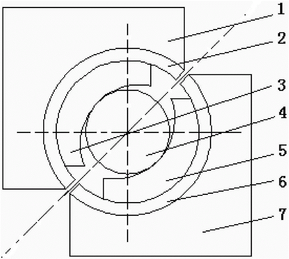
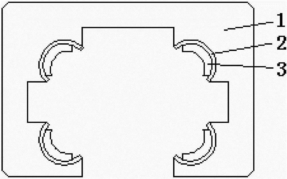
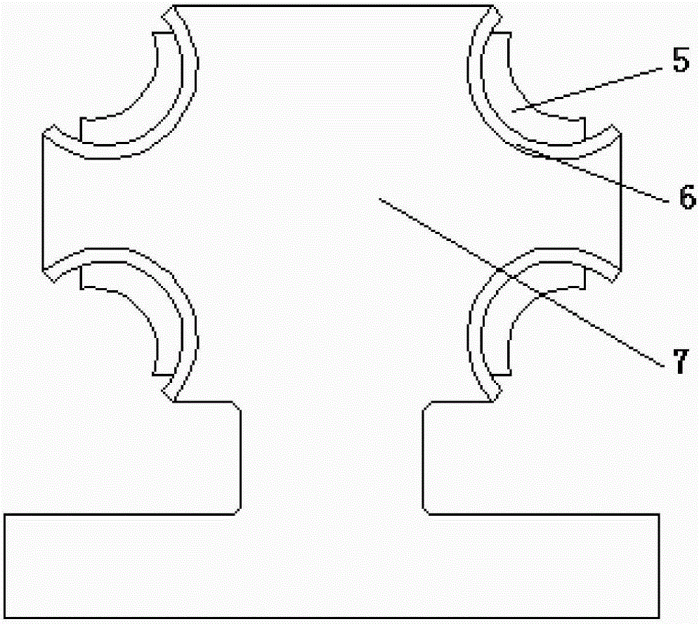
[0021] Such as Figure 1-8 As shown, a device that can detect the motion state of the ball in the rolling motion pair, the device includes a slider 1, a slider magnetic switch ring 2, a non-metallic slider raceway 3, a magnetic ball 4, a non-metallic guide rail raceway 5 , guide rail magnetic switch ring 6, guide rail 7, magnetic switch array 8, ball strong magnet 9.

[0022] Slider 1, slider magnetic switch ring 2, non-metallic slider raceway 3, the three are fixedly connected by keys or pins, and there is no relative movement between the three; non-metallic guide rail raceway 5, guide rail magnetic switch ring 6. The guide rail 7 is also connected and fixed by keys or pins, and there is no relative movement between the three; the slider 1 and the guide rail 7 cooperate to form a rolling motion pair. In the rolling motion pair, the slider 1 passes The ball moves linearly along the guide rail 7; the magnetic ball 4 and other balls roll between the non-metal slider raceway 3 a...


PUM


Abstract

A device that can detect the motion state of balls in a rolling motion pair, the device includes a slider, a slider magnetic switch ring, a non-metallic slider raceway, a magnetic ball, a non-metallic guide rail raceway, a guide rail magnetic switch ring, a guide rail, Magnetic switch array, ball strong magnet. The slider and the guide rail cooperate to form a rolling motion pair. In the rolling motion pair, the slider moves linearly along the guide rail through the balls; magnetic balls and other balls roll between the non-metallic slider raceway and the non-metallic guide rail raceway . When the magnetic ball rolls in the rolling motion pair, a part of the strong magnetism will pass through different magnetic switches respectively. The detection system can judge the path of the magnetic ball through the sequence of the switching signals sent by the magnetic sleeve and the coordinates of the magnetic switches. The inventive device has a simple structure, is easy to manufacture, can effectively detect the movement of the balls, and truly simulates the actual structure and force relationship of the rolling pair.

Description

technical field [0001] The invention relates to a device capable of detecting the motion state of a ball in a rolling kinematic pair, and belongs to the technical field of detection. Background technique [0002] The rolling motion pair is the main functional part of the CNC machine tool feed system, and its accuracy and performance determine the accuracy of the CNC machine tool feed system. In order to ensure the transmission accuracy of the rolling kinematic pair, a pre-tightened rolling kinematic pair is generally used. After the rolling kinematic pair actually works for a period of time, the friction and wear of the moving parts will lead to the loss of pre-tightening force and the degradation of the accuracy of the rolling kinematic pair. It is very important to analyze the accuracy degradation process of the rolling kinematic pair, and wear is one of the main reasons for the degradation of accuracy. You must know For the wear mechanism of the ball and the guide rail, ...

Claims


Application Information

Patent Timeline
Patent Type & Authority Patents(China)
IPC IPC(8): G01M13/02B23Q17/00
Inventor 张巍王民孔德顺高相胜
Owner BEIJING UNIV OF TECH
Why Eureka
Try Eureka